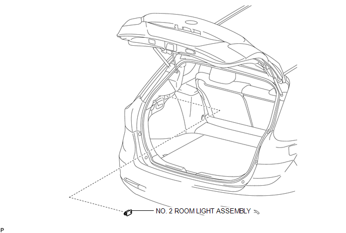
Toyota Venza: Luggage Compartment Room Light
Components
COMPONENTS
ILLUSTRATION
Removal
REMOVAL
PROCEDURE
1. REMOVE NO. 2 ROOM LIGHT ASSEMBLY
|
(a) Using a moulding remover, disengage the claw. |
|
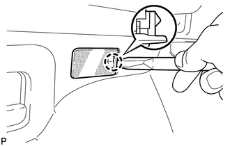
(b) Disconnect the connector and remove the No. 2 room light assembly.
Inspection
INSPECTION
PROCEDURE
1. INSPECT NO. 2 ROOM LIGHT ASSEMBLY
|
(a) Connect a positive (+) lead from the battery to terminal 1 and a negative (-) lead to terminal 2. |
|
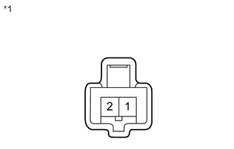
(b) Check that the light comes on.
OK:
Light comes on.
Text in Illustration|
*1 |
Component without harness connected (No. 2 Room Light Assembly) |
If the result is not as specified, replace the bulb or No. 2 room light assembly.
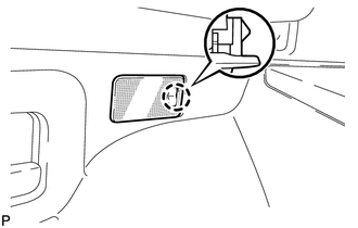
Installation
INSTALLATION
PROCEDURE
1. INSTALL NO. 2 ROOM LIGHT ASSEMBLY
(a) Connect the connector.
|
(b) Engage the claw to install the No. 2 room light assembly. |
|
 Door Unlock Detection Switch Circuit
DESCRIPTION
The main body ECU (driver side junction block assembly) detects the condition
of the door unlock detection switch.
WIRING DIAGRAM
PROCEDURE
1.
READ VALUE USI ...
 Personal Light
Components
COMPONENTS
ILLUSTRATION
Removal
REMOVAL
PROCEDURE
1. REMOVE MAP LIGHT ASSEMBLY
(a) Using a moulding remover, disengage the 2 claws and 2 clips.
Text in Illustrati ...
Other materials about Toyota Venza:
Room Light
Components
COMPONENTS
ILLUSTRATION
Removal
REMOVAL
PROCEDURE
1. REMOVE SPOT LIGHT ASSEMBLY
(a) Using a screwdriver with its tip wrapped with protective tape, disengage
the 8 claws to remove the 2 spot light lenses.
Text in Illust ...
Installation
INSTALLATION
PROCEDURE
1. INSTALL LUMBAR SUPPORT ADJUSTER ASSEMBLY
(a) Install the bush.
(b) Install the lumbar support adjuster assembly with the guide and 2
screws.
...
Regulations on the use of tire chains
• Regulations regarding the use of tire chains vary according to location and
type of road. Always check local regulations before installing chains.
• Retighten the chains after driving 1/4 - 1/2 mile (0.5 - 1.0 km).
- Tire chains
Observe the fo ...

0.1325