Toyota Venza: Passenger Airbag ON/OFF Indicator Circuit Malfunction (B1660/43)
DESCRIPTION
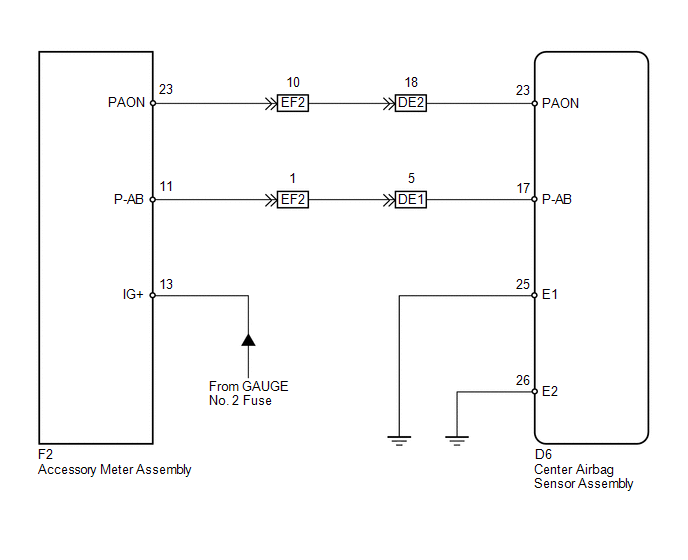
The passenger airbag ON/OFF indicator circuit consists of the center airbag sensor assembly and accessory meter assembly (passenger airbag ON/OFF indicator).
The passenger airbag ON/OFF indicator indicates the operation condition of the front passenger airbag and front seat belt pretensioner RH.
DTC B1660/43 is stored when a malfunction is detected in the passenger airbag ON/OFF indicator circuit.
|
DTC No. |
DTC Detection Condition |
Trouble Area |
|---|---|---|
|
B1660/43 |
|
|
WIRING DIAGRAM
CAUTION / NOTICE / HINT
HINT:
- Perform the simulation method by selecting check mode (Signal Check)
using the Techstream (See page
.gif) ).
).
- After selecting check mode (Signal Check), perform the simulation method
by wiggling each connector of the airbag system or driving the vehicle on
a city or rough road (See page ).
PROCEDURE
|
1. |
CHECK PASSENGER AIRBAG ON/OFF INDICATOR CONDITION |
(a) Turn the ignition switch to ON.
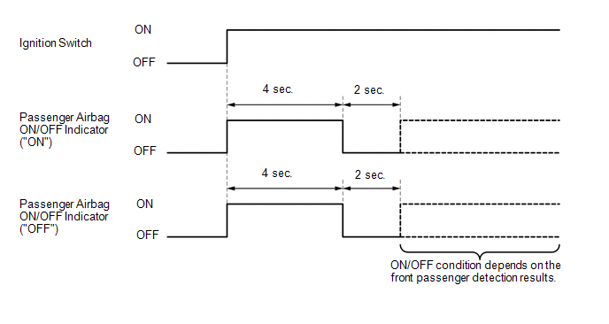
(b) Check the passenger airbag ON/OFF indicator operation.
HINT:
Refer to the normal condition of the passenger airbag ON/OFF indicator (See page
).
|
ON/OFF Indicator Illumination |
Proceed to |
|---|---|
|
Always ON |
A |
|
OFF |
B |
| B | .gif) |
GO TO STEP 9 |
|
.gif)
|
2. |
CHECK CONNECTORS |
(a) Turn the ignition switch off.
(b) Disconnect the cable from the negative (-) battery terminal, and wait for at least 90 seconds.
(c) Check that the connectors are properly connected to the center airbag sensor assembly and accessory meter assembly. Also check that the connectors that link the instrument panel wire, No. 2 instrument panel wire and No. 3 instrument panel wire are properly connected.
OK:
The connectors are properly connected.
HINT:
If the connectors are not connected securely, reconnect the connectors and proceed to the next inspection.
(d) Disconnect the connectors from the center airbag sensor assembly and accessory meter assembly. Also disconnect the connectors that link the instrument panel wire, No. 2 instrument panel wire and No. 3 instrument panel wire.
(e) Check that the terminals of connectors are not damaged.
OK:
The terminals are not deformed or damaged.
| NG | |
REPLACE WIRE HARNESS |
|
|
3. |
CHECK PASSENGER AIRBAG ON/OFF INDICATOR |
|
(a) Connect the connectors that link the instrument panel wire, No. 2 instrument panel wire and No. 3 instrument panel wire. |
|
.png)
(b) Connect the connector to the accessory meter assembly.
(c) Connect the cable to the negative (-) battery terminal.
(d) Turn the ignition switch to ON.
(e) Check the passenger airbag ON/OFF indicator operation.
OK:
The passenger airbag ON/OFF indicator does not come on.
| NG | |
GO TO STEP 5 |
|
|
4. |
CHECK CENTER AIRBAG SENSOR ASSEMBLY |
|
(a) Connect the connector to the center airbag sensor assembly. |
|
(b) Connect the cable to the negative (-) battery terminal.
(c) Turn the ignition switch to ON, and wait for at least 60 seconds.
(d) Clear the DTCs stored in memory (See page
).
(e) Turn the ignition switch off.
(f) Turn the ignition switch to ON, and wait for at least 60 seconds.
(g) Check for DTCs (See page ).
OK:
DTC B1660/43 is not output.
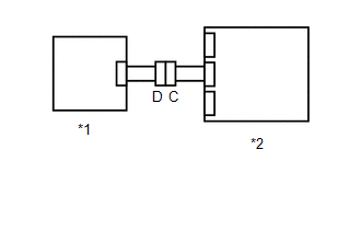
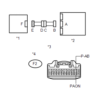
Text in Illustration|
*1 |
Accessory Meter Assembly |
|
*2 |
Center Airbag Sensor Assembly |
HINT:
Codes other than DTC B1660/43 may be output at this time, but they are not related to this check.
| OK | |
USE SIMULATION METHOD TO CHECK |
| NG | |
REPLACE CENTER AIRBAG SENSOR ASSEMBLY |
|
5. |
CHECK PASSENGER AIRBAG ON/OFF INDICATOR CIRCUIT (OPEN) |
(a) Turn the ignition switch off.
(b) Disconnect the cable from the negative (-) battery terminal, and wait for at least 90 seconds.
(c) Connect the connectors that link the instrument panel wire, No. 2 instrument panel wire and No. 3 instrument panel wire.
(d) Disconnect the connector from the accessory meter assembly.
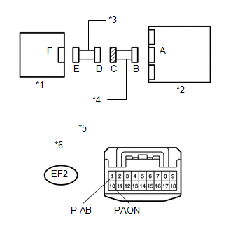
(e) Using SST, connect terminals 23 (PAON) and 17 (P-AB) of connector B.
NOTICE:
Do not forcibly insert SST into the terminals of the connector when connecting the wire.
SST: 09843-18040
(f) Measure the resistance according to the value(s) in the table below.
Standard Resistance:
|
Tester Connection |
Condition |
Specified Condition |
|---|---|---|
|
F2-23 (PAON) - F2-11 (P-AB) |
Always |
Below 1 Ω |
|
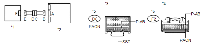
*1 |
Accessory Meter Assembly |
*2 |
Center Airbag Sensor Assembly |
|
*3 |
Front view of wire harness connector (to Center Airbag Sensor Assembly) |
*4 |
Front view of wire harness connector (to Accessory Meter Assembly) |
|
*5 |
Connector B |
*6 |
Connector E |
| NG | |
GO TO STEP 17 |
|
|
6. |
CHECK PASSENGER AIRBAG ON/OFF INDICATOR CIRCUIT (SHORT) |
|
(a) Disconnect SST from connector B. |
|
(b) Measure the resistance according to the value(s) in the table below.
Standard Resistance:
|
Tester Connection |
Condition |
Specified Condition |
|---|---|---|
|
F2-23 (PAON) - F2-11 (P-AB) |
Always |
1 MΩ or higher |
|
*1 |
Accessory Meter Assembly |
|
*2 |
Center Airbag Sensor Assembly |
|
*3 |
Front view of wire harness connector (to Accessory Meter Assembly) |
|
*4 |
Connector E |
| NG | |
GO TO STEP 18 |
|
|
7. |
CHECK PASSENGER AIRBAG ON/OFF INDICATOR CIRCUIT (SHORT TO GROUND) |
|
(a) Measure the resistance according to the value(s) in the table below. Standard Resistance:
|
|
| NG | |
GO TO STEP 19 |
|
|
8. |
CHECK PASSENGER AIRBAG ON/OFF INDICATOR CIRCUIT (SHORT TO B+) |
|
(a) Connect the cable to the negative (-) battery terminal. |
|
(b) Turn the ignition switch to ON.
(c) Measure the voltage according to the value(s) in the table below.
Standard Voltage:
|
Tester Connection |
Switch Condition |
Specified Condition |
|---|---|---|
|
F2-23 (PAON) - Body ground |
Ignition switch ON |
Below 1 V |
|
F2-11 (P-AB) - Body ground |
Ignition switch ON |
Below 1 V |
|
*1 |
Accessory Meter Assembly |
|
*2 |
Center Airbag Sensor Assembly |
|
*3 |
Front view of wire harness connector (to Accessory Meter Assembly) |
|
*4 |
Connector E |
| OK | |
REPLACE ACCESSORY METER ASSEMBLY |
| NG | |
GO TO STEP 20 |
|
9. |
CHECK CONNECTORS |
(a) Turn the ignition switch off.
(b) Disconnect the cable from the negative (-) battery terminal, and wait for at least 90 seconds.
(c) Check that the connectors are properly connected to the center airbag sensor assembly and accessory meter assembly. Also check that the connectors that link the instrument panel wire, No. 2 instrument panel wire and No. 3 instrument panel wire are properly connected.
OK:
The connectors are properly connected.
HINT:
If the connectors are not connected securely, reconnect the connectors and proceed to the next inspection.
(d) Disconnect the connectors from the center airbag sensor assembly and accessory meter assembly. Also disconnect the connectors that link the instrument panel wire, No. 2 instrument panel wire and No. 3 instrument panel wire.
(e) Check that the terminals of connectors are not damaged.
OK:
The terminals are not deformed or damaged.
| NG | |
REPLACE WIRE HARNESS |
|
|
10. |
CHECK PASSENGER AIRBAG ON/OFF INDICATOR CIRCUIT (OPEN) |
(a) Connect the connectors that link the instrument panel wire, No. 2 instrument panel wire and No. 3 instrument panel wire.
(b) Using SST, connect terminals 23 (PAON) and 17 (P-AB) of connector B.
NOTICE:
Do not forcibly insert SST into the terminals of the connector when connecting the wire.
SST: 09843-18040
(c) Measure the resistance according to the value(s) in the table below.
Standard Resistance:
|
Tester Connection |
Condition |
Specified Condition |
|---|---|---|
|
F2-23 (PAON) - F2-11 (P-AB) |
Always |
Below 1 Ω |
|
*1 |
Accessory Meter Assembly |
*2 |
Center Airbag Sensor Assembly |
|
*3 |
Front view of wire harness connector (to Center Airbag Sensor Assembly) |
*4 |
Front view of wire harness connector (to Accessory Meter Assembly) |
|
*5 |
Connector B |
*6 |
Connector E |
| NG | |
GO TO STEP 17 |
|
|
11. |
CHECK PASSENGER AIRBAG ON/OFF INDICATOR CIRCUIT (SHORT) |
|
(a) Disconnect SST from connector B. |
|
(b) Measure the resistance according to the value(s) in the table below.
Standard Resistance:
|
Tester Connection |
Condition |
Specified Condition |
|---|---|---|
|
F2-23 (PAON) - F2-11 (P-AB) |
Always |
1 MΩ or higher |
|
*1 |
Accessory Meter Assembly |
|
*2 |
Center Airbag Sensor Assembly |
|
*3 |
Front view of wire harness connector (to Accessory Meter Assembly) |
|
*4 |
Connector E |
| NG | |
GO TO STEP 18 |
|
|
12. |
CHECK PASSENGER AIRBAG ON/OFF INDICATOR CIRCUIT (SHORT TO GROUND) |
|
(a) Measure the resistance according to the value(s) in the table below. Standard Resistance:
|
|
| NG | |
GO TO STEP 19 |
|
|
13. |
CHECK PASSENGER AIRBAG ON/OFF INDICATOR CIRCUIT (SHORT TO B+) |
|
(a) Connect the cable to the negative (-) battery terminal. |
|
(b) Turn the ignition switch to ON.
(c) Measure the voltage according to the value(s) in the table below.
Standard Voltage:
|
Tester Connection |
Switch Condition |
Specified Condition |
|---|---|---|
|
F2-23 (PAON) - Body ground |
Ignition switch ON |
Below 1 V |
|
F2-11 (P-AB) - Body ground |
Ignition switch ON |
Below 1 V |
|
*1 |
Accessory Meter Assembly |
|
*2 |
Center Airbag Sensor Assembly |
|
*3 |
Front view of wire harness connector (to Accessory Meter Assembly) |
|
*4 |
Connector E |
| NG | |
GO TO STEP 20 |
|
|
14. |
CHECK ACCESSORY METER ASSEMBLY (SOURCE VOLTAGE) |
|
(a) Turn the ignition switch to ON. |
|
(b) Measure the voltage according to the value(s) in the table below.
Standard Voltage:
|
Tester Connection |
Switch Condition |
Specified Condition |
|---|---|---|
|
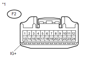
F2-13 (IG+) - Body ground |
Ignition switch ON |
10 to 14 V |
|
*1 |
Front view of wire harness connector (to Accessory Meter Assembly) |
| NG | |
REPLACE WIRE HARNESS (ACCESSORY METER ASSEMBLY - BATTERY) OR BATTERY |
|
|
15. |
CHECK PASSENGER AIRBAG ON/OFF INDICATOR |
|
(a) Turn the ignition switch off. |
|
(b) Disconnect the cable from the negative (-) battery terminal, and wait for at least 90 seconds.
(c) Connect the connector to the accessory meter assembly.
(d) Connect the cable to the negative (-) battery terminal.
(e) Turn the ignition switch to ON.
(f) Check the indicator according to the conditions in the table below.
|
Tester Connection |
Switch Condition |
Passenger Airbag ON/OFF Indicator |
|---|---|---|
|
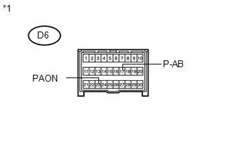
D6-23 (PAON) - Body ground |
Ignition switch ON |
"ON" comes on |
|
D6-17 (P-AB) - Body ground |
Ignition switch ON |
"OFF" comes on |
|
*1 |
Front view of wire harness connector (to Center Airbag Sensor Assembly) |
| NG | |
REPLACE ACCESSORY METER ASSEMBLY |
|
|
16. |
CHECK CENTER AIRBAG SENSOR ASSEMBLY |
|
(a) Turn the ignition switch off. |
|
(b) Disconnect the cable from the negative (-) battery terminal, and wait for at least 90 seconds.
(c) Connect the connector to the center airbag sensor assembly.
(d) Connect the cable to the negative (-) battery terminal.
(e) Turn the ignition switch to ON, and wait for at least 60 seconds.
(f) Clear the DTCs stored in memory (See page
).
(g) Turn the ignition switch off.
(h) Turn the ignition switch to ON, and wait for at least 60 seconds.
(i) Check for DTCs (See page ).
OK:
DTC B1660/43 is not output.
Text in Illustration|
*1 |
Accessory Meter Assembly |
|
*2 |
Center Airbag Sensor Assembly |
HINT:
Codes other than DTC B1660/43 may be output at this time, but they are not related to this check.
| OK | |
USE SIMULATION METHOD TO CHECK |
| NG | |
REPLACE CENTER AIRBAG SENSOR ASSEMBLY |
|
17. |
CHECK WIRE HARNESS (OPEN) |
(a) Disconnect the wire harness from the No. 3 instrument panel wire.
HINT:
SST has already been inserted into connector B.
(b) Measure the resistance according to the value(s) in the table below.
Standard Resistance:
|
Tester Connection |
Condition |
Specified Condition |
|---|---|---|
|
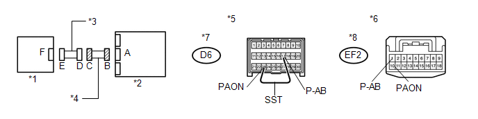
EF2-10 (PAON) - EF2-1 (P-AB) |
Always |
Below 1 Ω |
|
*1 |
Accessory Meter Assembly |
*2 |
Center Airbag Sensor Assembly |
|
*3 |
No. 3 Instrument Panel Wire |
*4 |
Wire Harness |
|
*5 |
Front view of wire harness connector (to Center Airbag Sensor Assembly) |
*6 |
Front view of wire harness connector (to No. 3 Instrument Panel Wire) |
|
*7 |
Connector B |
*8 |
Connector C |
| OK | |
REPLACE NO. 3 INSTRUMENT PANEL WIRE |
| NG | |
REPLACE WIRE HARNESS |
|
18. |
CHECK WIRE HARNESS (SHORT) |
|
(a) Disconnect the wire harness from the No. 3 instrument panel wire. |
|
(b) Measure the resistance according to the value(s) in the table below.
Standard Resistance:
|
Tester Connection |
Condition |
Specified Condition |
|---|---|---|
|
EF2-10 (PAON) - EF2-1 (P-AB) |
Always |
1 MΩ or higher |
|
*1 |
Accessory Meter Assembly |
|
*2 |
Center Airbag Sensor Assembly |
|
*3 |
No. 3 Instrument Panel Wire |
|
*4 |
Wire Harness |
|
*5 |
Front view of wire harness connector (to No. 3 Instrument Panel Wire) |
|
*6 |
Connector C |
| OK | |
REPLACE NO. 3 INSTRUMENT PANEL WIRE |
| NG | |
REPLACE WIRE HARNESS |
|
19. |
CHECK WIRE HARNESS (SHORT TO GROUND) |
|
(a) Disconnect the wire harness from the No. 3 instrument panel wire. |
|
(b) Measure the resistance according to the value(s) in the table below.
Standard Resistance:
|
Tester Connection |
Condition |
Specified Condition |
|---|---|---|
|
EF2-10 (PAON) - Body ground |
Always |
1 MΩ or higher |
|
EF2-1 (P-AB) - Body ground |
Always |
1 MΩ or higher |
|
*1 |
Accessory Meter Assembly |
|
*2 |
Center Airbag Sensor Assembly |
|
*3 |
No. 3 Instrument Panel Wire |
|
*4 |
Wire Harness |
|
*5 |
Front view of wire harness connector (to No. 3 Instrument Panel Wire) |
|
*6 |
Connector C |
| OK | |
REPLACE NO. 3 INSTRUMENT PANEL WIRE |
| NG | |
REPLACE WIRE HARNESS |
|
20. |
CHECK WIRE HARNESS (SHORT TO B+) |
|
(a) Turn the ignition switch off. |
|
(b) Disconnect the cable from the negative (-) battery terminal, and wait for at least 90 seconds.
(c) Disconnect the wire harness from the No. 3 instrument panel wire.
(d) Connect the cable to the negative (-) battery terminal.
(e) Turn the ignition switch to ON.
(f) Measure the voltage according to the value(s) in the table below.
Standard Voltage:
|
Tester Connection |
Switch Condition |
Specified Condition |
|---|---|---|
|
EF2-10 (PAON) - Body ground |
Ignition switch ON |
Below 1 V |
|
EF2-1 (P-AB) - Body ground |
Ignition switch ON |
Below 1 V |
|
*1 |
Accessory Meter Assembly |
|
*2 |
Center Airbag Sensor Assembly |
|
*3 |
No. 3 Instrument Panel Wire |
|
*4 |
Wire Harness |
|
*5 |
Front view of wire harness connector (to No. 3 Instrument Panel Wire) |
|
*6 |
Connector C |
| OK | |
REPLACE NO. 3 INSTRUMENT PANEL WIRE |
| NG | |
REPLACE WIRE HARNESS |
 Diagnostic Trouble Code Chart
DIAGNOSTIC TROUBLE CODE CHART
If a trouble code is displayed during the DTC check, check the circuit listed
for the code in the table below (refer to the appropriate page).
HINT:
When the ...
 Door Side Airbag Sensor RH Malfunction (B1690/15)
DESCRIPTION
The side collision sensor RH circuit (to determine deployment of the front seat
side airbag assembly RH and curtain shield airbag assembly RH) is composed of the
center airbag sensor ...
Other materials about Toyota Venza:
Lost Communication with "Door Control Module B" (U0200)
DESCRIPTION
DTC No.
DTC Detection Condition
Trouble Area
U0200
No communication from the outer mirror control ECU assembly (for driver
side).
Outer mirror control ECU assem ...
Noise Occurs
PROCEDURE
1.
CHECK NOISE CONDITION
(a) Check from which direction the noise comes (front left or right, or rear
left or right).
OK:
The location of the noise source can be determined.
NG
GO TO STEP 3
...
Removal
REMOVAL
PROCEDURE
1. REMOVE REAR WHEELS
2. SEPARATE REAR STABILIZER LINK ASSEMBLY LH
(a) Remove the nut and separate the rear stabilizer link assembly LH
from the rear stabilizer bar.
Text in Illustration
*1
...

0.1609