Toyota Venza: Parts Location
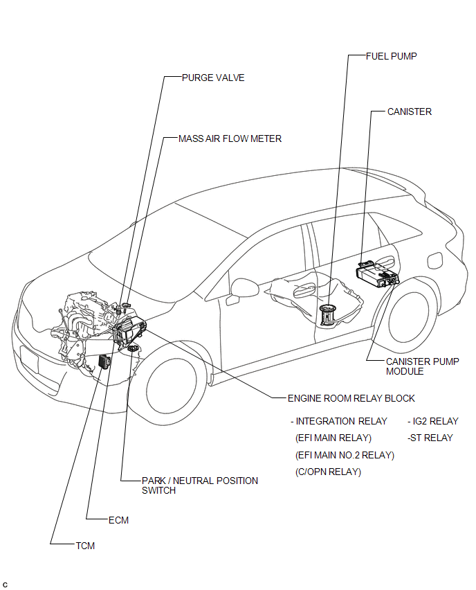
PARTS LOCATION
ILLUSTRATION
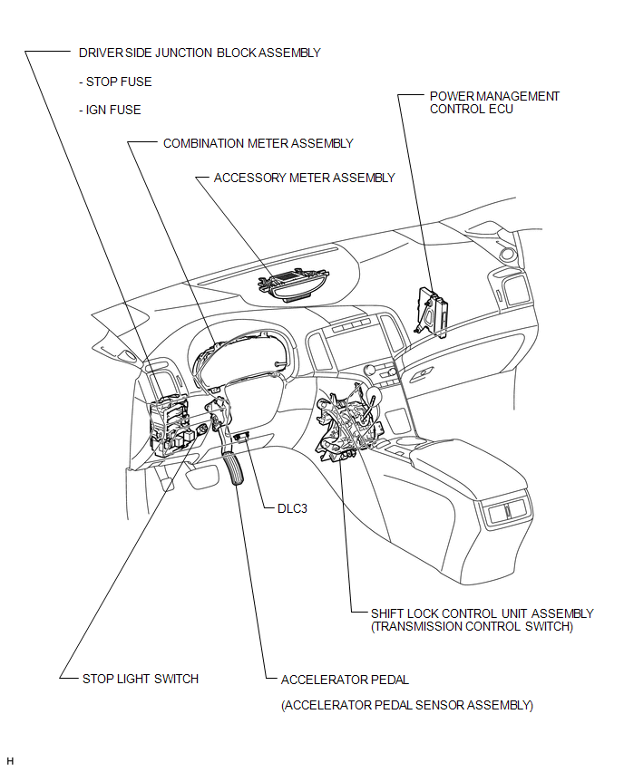
ILLUSTRATION
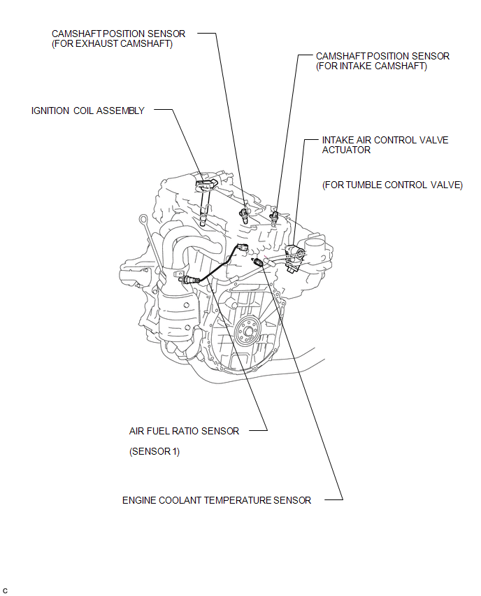
ILLUSTRATION
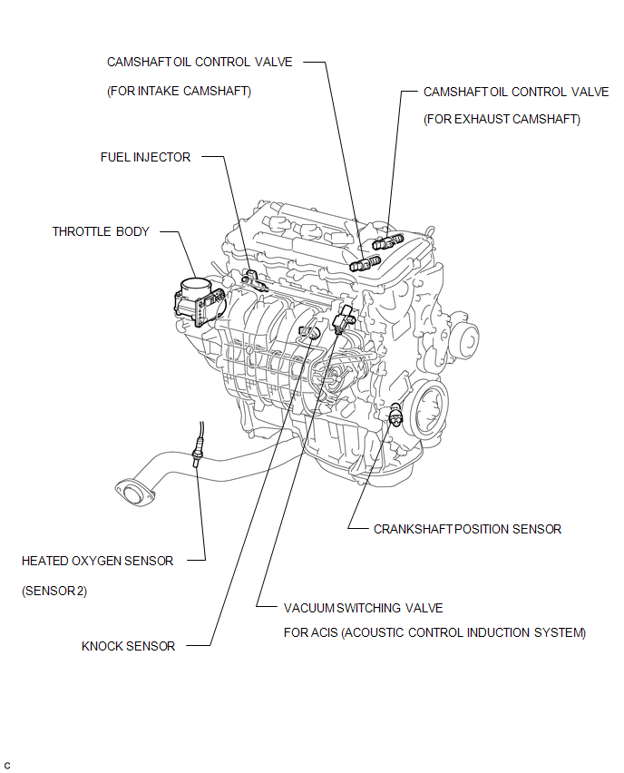
ILLUSTRATION
 Definition Of Terms
DEFINITION OF TERMS
Term
Definition
Monitor Description
Description of what the ECM monitors and how it detects malfunctions
(monitoring purpose ...
 How To Proceed With Troubleshooting
CAUTION / NOTICE / HINT
HINT:
*: Use the Techstream.
PROCEDURE
1.
VEHICLE BROUGHT TO WORKSHOP
NEXT
...
Other materials about Toyota Venza:
Charge Warning Light Comes ON while Driving
PROCEDURE
1.
CHECK LOCK FUNCTION OF CLUTCH PULLEY
(a) Check the lock function with the pulley installed in the vehicle.
(1) Visually check that the rotor in the generator operates with the engine started.
(b) Check the lock ...
Open in Inside Luggage Compartment Electrical Key Oscillator Circuit (B27A7)
DESCRIPTION
The certification ECU (smart key ECU assembly) generates a request signal and
sends it to the indoor electrical key oscillator (for rear floor). To detect the
key inside the cabin, the indoor electrical key oscillator (for rear floor) creates ...
Power Management Control Ecu
Components
COMPONENTS
ILLUSTRATION
Removal
REMOVAL
PROCEDURE
1. REMOVE FRONT DOOR SCUFF PLATE RH
2. REMOVE COWL SIDE TRIM SUB-ASSEMBLY RH
3. REMOVE NO. 2 INSTRUMENT PANEL UNDER COVER SUB-ASSEMBLY
4. REMOVE LOWER INSTRUMENT PANEL SUB-ASS ...

0.1138