Toyota Venza: Parts Location
PARTS LOCATION
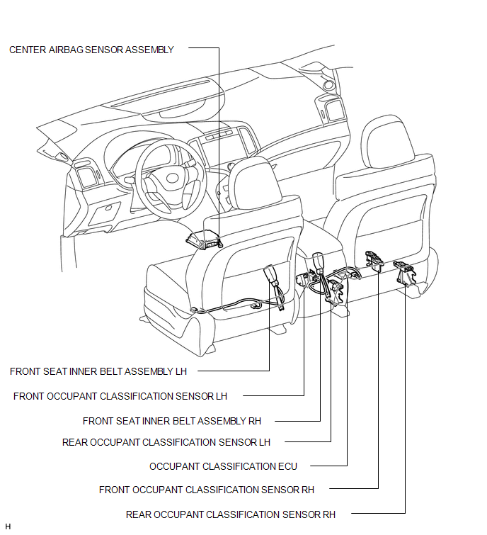
ILLUSTRATION
ILLUSTRATION
 Precaution
PRECAUTION
NOTICE:
When disconnecting the cable from the negative (-) battery terminal, initialize
the following systems after the cable is reconnected.
System Name
See Proc ...
 System Description
SYSTEM DESCRIPTION
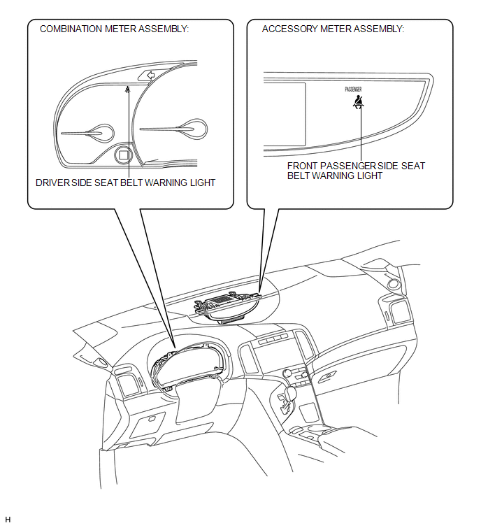
1. SEAT BELT WARNING SYSTEM DESCRIPTION
If a seat belt is not fastened, this system flashes the seat belt warning light
or sounds the seat belt warning buzzer as a reminder.
(a ...
Other materials about Toyota Venza:
Transmission Wire(when Using The Engine Support Bridge)
Components
COMPONENTS
ILLUSTRATION
Installation
INSTALLATION
PROCEDURE
1. INSTALL TRANSMISSION WIRE
(a) Coat the O-ring with ATF.
(b) Coat the bolt with ATF.
(c) Install the transmission ...
Installation
INSTALLATION
CAUTION / NOTICE / HINT
HINT:
When installing new name plates and emblem, heat the vehicle body, name plates
and emblem using a heat light.
Heating Temperature
Item
Temperature
Vehicle Body
...
Power back door switch (vehicles with power back door)
Push the switch to close.
Pressing the switch again while the power back door is closing will cause it
to open again.
However, the reverse operation cannot be performed for the first second after
pressing the switch to close the door.
The back door ca ...

0.1609