Toyota Venza: Installation
INSTALLATION
PROCEDURE
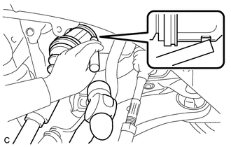
1. INSTALL FRONT DRIVE SHAFT ASSEMBLY LH
|
(a) Align the splines of the shaft and install the drive shaft assembly LH using a brass bar and a hammer. NOTICE:
|
|
(b) Apply a total of 0.1 to 0.3g (0.00353 to 0.0105 oz.) of Toyota Body Grease W to the 8 areas shown in the illustration.
.png) Text in Illustration
Text in Illustration
.png) |
Toyota Body Grease W |
NOTICE:
Do not apply grease to the serrations or installation hole of the front speed sensor.
2. INSTALL FRONT DRIVE SHAFT ASSEMBLY RH (for 2WD)
(a) Install the front drive shaft assembly RH.
|
(b) Install the bearing bracket hole snap ring and a new bolt. Torque: 32 N·m {330 kgf·cm, 24 ft·lbf} NOTICE:
|
|
.png)
(c) Apply a total of 0.1 to 0.3g (0.00353 to 0.0105 oz.) of Toyota Body Grease W to the 8 areas shown in the illustration.
 Text in Illustration
|
|
Toyota Body Grease W |
NOTICE:
Do not apply grease to the serrations or installation hole of the front speed sensor.
3. INSTALL FRONT DRIVE SHAFT ASSEMBLY RH (for AWD)
(a) Install the front drive shaft assembly RH.
|
(b) Install the bearing bracket hole snap ring and a new bolt. Torque: 32 N·m {330 kgf·cm, 24 ft·lbf} NOTICE:
|
|
.png)
(c) Apply a total of 0.1 to 0.3g (0.00353 to 0.0105 oz.) of Toyota Body Grease W to the 8 areas shown in the illustration.
Text in Illustration
|
|
Toyota Body Grease W |
NOTICE:
Do not apply grease to the serrations or installation hole of the front speed sensor.
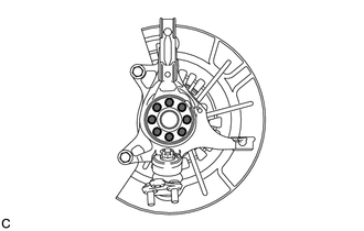
4. INSTALL FRONT AXLE ASSEMBLY
.gif)
5. INSTALL FRONT LOWER SUSPENSION ARM
6. CONNECT TIE ROD ASSEMBLY
7. INSTALL FRONT SPEED SENSOR
|
(a) Install the front speed sensor and front flexible hose with the bolt. Torque: 19 N·m {194 kgf·cm, 14 ft·lbf} NOTICE:
|
|
.png)
|
(b) Install the front speed sensor to the steering knuckle with the bolt. Torque: 8.5 N·m {87 kgf·cm, 75 in·lbf} NOTICE:
|
|
.png)
8. INSTALL FRONT STABILIZER LINK ASSEMBLY
9. INSTALL FRONT AXLE SHAFT NUT
(a) Clean the threaded parts on the front drive shaft and a new front axle shaft nut using a non-residue solvent.
HINT:
- Be sure to perform this work for a new drive shaft.
- Keep the threaded parts free of oil and foreign matter.
|
(b) Install the new front axle shaft nut. Torque: 294 N·m {2998 kgf·cm, 217 ft·lbf} |
|
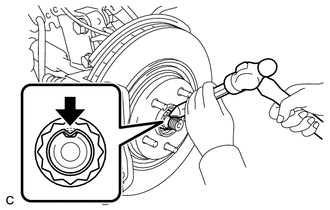
(c) Using a chisel and hammer, stake the front axle shaft nut.
10. INSTALL FRONT WHEELS
Torque:
103 N·m {1050 kgf·cm, 76 ft·lbf}
11. ADD TRANSFER OIL (for AWD)
12. ADJUST TRANSFER OIL (for AWD)
13. ADD AUTOMATIC TRANSAXLE FLUID
HINT:
- for U660E: See page
- for U660F: See page
- for U760E: See page
- for U760F: See page
14. ADJUST FRONT WHEEL ALIGNMENT
HINT:
(See page )
15. CHECK ABS SPEED SENSOR SIGNAL
HINT:
(See page )
 Reassembly
REASSEMBLY
PROCEDURE
1. INSTALL BEARING BRACKET HOLE SNAP RING (for RH Side)
(a) Install a new bearing bracket hole snap ring to the front drive shaft assembly
RH.
2. INSTALL FRONT DRIVE SHAFT B ...

Other materials about Toyota Venza:
Installation
INSTALLATION
PROCEDURE
1. CLEAN FRONT SIDE FIX WINDOW ASSEMBLY
(a) Clean the outer edges of the front side fix window assembly with
a non-residue solvent.
NOTICE:
Do not touch the glass surface after cleaning it.
Be c ...
Transmission Range Sensor Circuit Malfunction (PRNDL Input) (P0705)
DESCRIPTION
The park/neutral position switch detects the shift lever position and sends signals
to the TCM.
DTC No.
DTC Detection Condition
Trouble Area
P0705
(A) Any 2 or more signals of the fol ...
Diagnosis System
DIAGNOSIS SYSTEM
1. ECUS OR SENSORS WHICH COMMUNICATE THROUGH CAN COMMUNICATION SYSTEM
(a) CAN No. 1 Bus
(1) ECM
(2) Main body ECU (Driver side junction block)
(3) Combination meter
(4) Power steering ECU
(5) Air conditioning amplifier*3
(6) Center air ...

0.1509