Toyota Venza: Parts Location
PARTS LOCATION
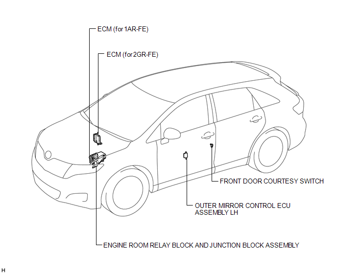
ILLUSTRATION
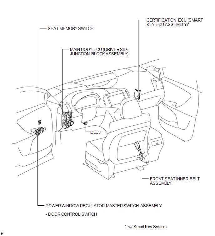
ILLUSTRATION
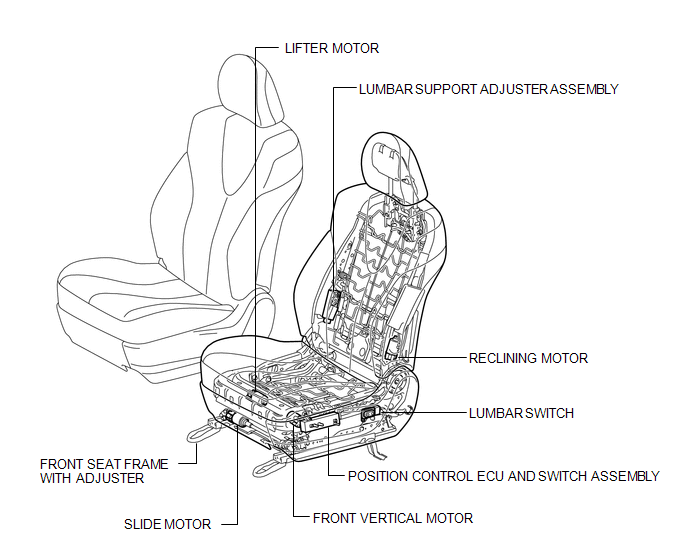
ILLUSTRATION

 Precaution
PRECAUTION
1. PRECAUTION FOR DISCONNECTING CABLE FROM NEGATIVE BATTERY TERMINAL
NOTICE:
When disconnecting the cable from the negative (-) battery terminal, initialize
the following system after ...
Other materials about Toyota Venza:
Front Passenger Side Power Window does not Operate with Front Passenger Side
Power Window Switch
DESCRIPTION
When the engine is running or the ignition switch is ON, the power window regulator
motor assembly (for front passenger side) is operated by the power window regulator
switch assembly (for front passenger side). The power window regulator moto ...
Sliding Roof does not Move by Operating Sliding Roof Control Switch
DESCRIPTION
The sliding roof ECU (sliding roof drive gear sub-assembly) receives switch slide
and tilt signals and drives its built-in motor.
WIRING DIAGRAM
CAUTION / NOTICE / HINT
NOTICE:
Inspect the fuses for circuits related to this system ...
Rear Speed Sensor RH Circuit (C0210/33,C0215/34,C1273/73,C1274/74,C1332/38,C1333/39)
DESCRIPTION
The speed sensor detects the wheel speed and sends the appropriate signals to
the skid control ECU. These signals are used for the ABS control system.
Speed sensor rotors have rows of alternating N and S magnetic poles (for 2WD)
or 48 serrati ...

0.1556