
Toyota Venza: Parts Location
PARTS LOCATION
ILLUSTRATION
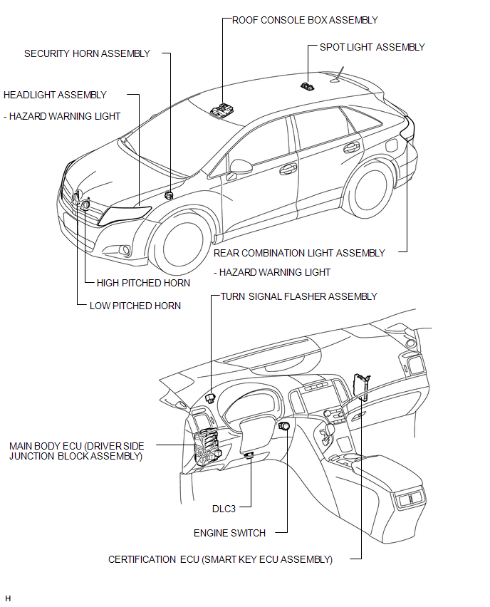
ILLUSTRATION
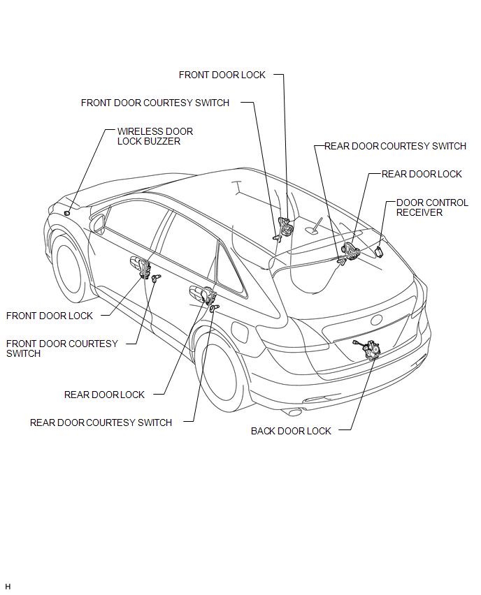
 Precaution
PRECAUTION
1. PRECAUTION FOR DISCONNECTING THE BATTERY CABLE
NOTICE:
When disconnecting the cable from the negative (-) battery terminal, initialize
the following systems after the terminal is re ...
 System Description
SYSTEM DESCRIPTION
1. WIRELESS DOOR LOCK CONTROL SYSTEM
The wireless door lock control system can be used to lock and unlock all doors
from a distance. The system is controlled by a door control t ...
Other materials about Toyota Venza:
Oxygen (A/F) Sensor Signal Stuck Lean (Bank 1 Sensor 1) (P2195,P2196)
DESCRIPTION
HINT:
Although the DTC titles say oxygen sensor, these DTCs relate to the
air fuel ratio sensor.
Sensor 1 refers to the sensor mounted in front of the three-way catalytic
converter and located near the engine assembly.
...
Installation
INSTALLATION
PROCEDURE
1. INSTALL FRONT SEAT ASSEMBLY
(a) Place the front seat assembly in the cabin.
NOTICE:
Be careful not to damage the vehicle body.
(b) Connect each connector under the front seat assembly.
(c) Connect the cable to the negative (-) ...
Components
COMPONENTS
ILLUSTRATION
ILLUSTRATION
ILLUSTRATION
ILLUSTRATION
ILLUSTRATION
ILLUSTRATION
ILLUSTRATION
ILLUSTRATION
ILLUSTRATION
ILLUSTRATION
...

0.1389