Toyota Venza: Parts Location
PARTS LOCATION
ILLUSTRATION
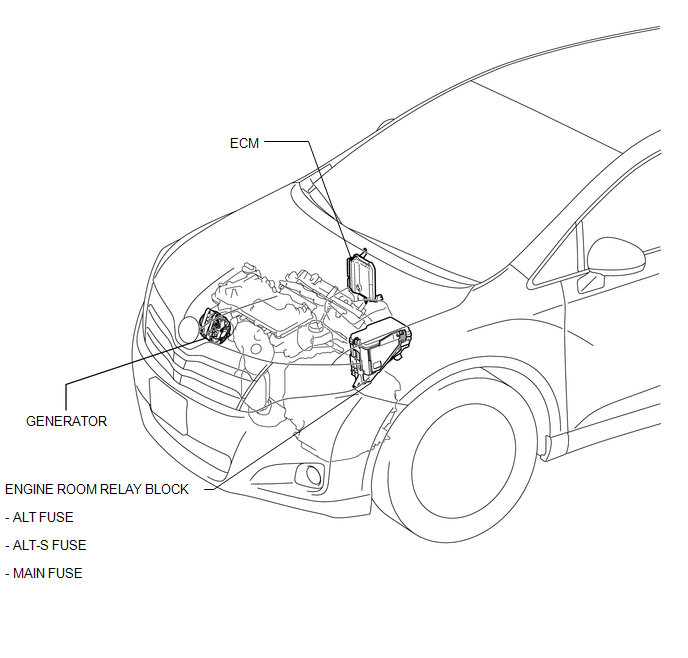
ILLUSTRATION
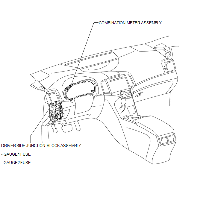
 Charging System
...
 Precaution
PRECAUTION
1. Check that the battery cables are connected to the correct terminals.
2. Disconnect the battery cables when the battery is given a quick charge.
3. Do not perform tests with a high vo ...
Other materials about Toyota Venza:
Atf Temperature Sensor(when Using The Engine Support Bridge)
Components
COMPONENTS
ILLUSTRATION
Inspection
INSPECTION
PROCEDURE
1. INSPECT ATF TEMPERATURE SENSOR ASSEMBLY
(a) Measure the resistance according to the value(s) in the table below.
Standard Resistance:
Tester C ...
Diagnosis System
DIAGNOSIS SYSTEM
1. DESCRIPTION
When troubleshooting OBD II (On-Board Diagnostics) vehicles, an OBD
II scan tool (complying with SAE J1987) must be connected to the DLC3 (Data
Link Connector 3) of the vehicle. Various data in the vehicle ECM ( ...
Removal
REMOVAL
CAUTION / NOTICE / HINT
HINT:
Use the same procedure for the RH side and LH side.
The procedure listed below is for the LH side.
PROCEDURE
1. REMOVE REAR WHEEL
2. REMOVE DECK SIDE TRIM
(a) Disengage the 5 claws, and ...

0.1407