Toyota Venza: Operation Check
OPERATION CHECK
1. CHECK WINDOW LOCK SWITCH
HINT:
Before performing the window lock switch operation check, make sure that the window lock switch is off (the switch is not pushed in).
(a) Check that the front passenger and rear windows cannot be operated from each power window regulator switch assembly (front passenger side, rear LH side or rear RH side) when the window lock switch of the power window regulator master switch assembly is pushed in.
OK:
Front passenger and rear windows are disabled.
HINT:
Even when the window lock switch of the power window regulator master switch assembly is pushed in, remote manual up and down and auto up and down functions can be operated.
(b) Check that the front passenger and rear windows can be operated from each power window regulator switch assembly (front passenger side, rear LH side or rear RH side) when the window lock switch of the power window regulator master switch assembly is pushed in again.
OK:
Front passenger and rear windows operate normally.
2. CHECK MANUAL UP / DOWN FUNCTION
(a) Check that the driver side power window operates as follows:
OK|
Condition |
Master Switch |
Switch Operation |
Power Window |
|---|---|---|---|
|
Ignition switch ON |
Driver side |
Pulled halfway up |
UP (Closes) |
|
Pushed halfway down |
DOWN (Opens) |
(b) Check that the front passenger side window and rear power windows operate as follows:
OK|
Condition |
Regulator Switch |
Switch Operation |
Power Window |
|---|---|---|---|
|
Front passenger side |
Pulled halfway up |
UP (Closes) |
|
Pushed halfway down |
DOWN (Opens) |
||
|
Rear LH side |
Pulled halfway up |
UP (Closes) |
|
|
Pushed halfway down |
DOWN (Opens) |
||
|
Rear RH side |
Pulled halfway up |
UP (Closes) |
|
|
Pushed halfway down |
DOWN (Opens) |
3. CHECK AUTO UP / DOWN FUNCTION
(a) Check that the driver side power window operates as follows:
OK|
Condition |
Master Switch |
Switch Operation |
Power Window |
|---|---|---|---|
|
Ignition switch ON |
Driver side |
Pulled up (One touch operation) |
AUTO UP (Closes) |
|
Pushed down (One touch operation) |
AUTO DOWN (Opens) |
(b) Check that the front passenger side window and rear power windows operate as follows:
OK|
Condition |
Regulator Switch |
Switch Operation |
Power Window |
|---|---|---|---|
|
Front passenger side |
Pulled up (One touch operation) |
AUTO UP (Closes) |
|
Pushed down (One touch operation) |
AUTO DOWN (Opens) |
||
|
Rear LH side |
Pulled up (One touch operation) |
AUTO UP (Closes) |
|
|
Pushed down (One touch operation) |
AUTO DOWN (Opens) |
||
|
Rear RH side |
Pulled up (One touch operation) |
AUTO UP (Closes) |
|
|
Pushed down (One touch operation) |
AUTO DOWN (Opens) |
4. CHECK REMOTE MANUAL UP / DOWN FUNCTION
(a) Check that the front passenger side window and rear power windows operate as follows:
OK|
Condition |
Master Switch |
Switch Operation |
Power Window |
|---|---|---|---|
|
Ignition switch ON |
Front passenger side |
Pulled halfway up |
UP (Closes) |
|
Pushed halfway down |
DOWN (Opens) |
||
|
Rear LH side |
Pulled halfway up |
UP (Closes) |
|
|
Pushed halfway down |
DOWN (Opens) |
||
|
Rear RH side |
Pulled halfway up |
UP (Closes) |
|
|
Pushed halfway down |
DOWN (Opens) |
5. CHECK REMOTE AUTO UP / DOWN FUNCTION
(a) Check that the front passenger side window and rear power windows operate as follows:
OK|
Condition |
Master Switch |
Switch Operation |
Power Window |
|---|---|---|---|
|
Ignition switch ON |
Front passenger side |
Pulled up (One touch operation) |
AUTO UP (Closes) |
|
Pushed down (One touch operation) |
AUTO DOWN (Opens) |
||
|
Rear LH side |
Pulled up (One touch operation) |
AUTO UP (Closes) |
|
|
Pushed down (One touch operation) |
AUTO DOWN (Opens) |
||
|
Rear RH side |
Pulled up (One touch operation) |
AUTO UP (Closes) |
|
|
Pushed down (One touch operation) |
AUTO DOWN (Opens) |
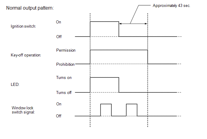
6. CHECK POWER WINDOW OPERATION FUNCTION AFTER IGNITION SWITCH IS TURNED OFF
(a) Check that all the power windows can be operated with the power window regulator master switch assembly after the ignition switch is turned off.
(b) Check that the key-off operation function does not operate after the driver door or front passenger side door is opened.
(c) Check that all the power windows cannot be operated after more than approximately 45 seconds have elapsed since the ignition switch was turned off.
7. CHECK JAM PROTECTION FUNCTION
(a) Check the basic function.
CAUTION:
Do not put your fingers between the door frame and door glass to check the jam protection function. Also, prevent any part of your body from being caught during inspection.
HINT:
The jam protection function is operative during both the auto up and manual up operations while the engine is running or the ignition switch is ON, and also 45 sec. have elapsed after the ignition switch is turned off.
(1) Fully open the window.
(2) Set a thick book wrapped with a piece of cloth near the window fully closed position.
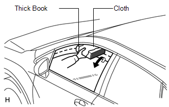
(3) Operate the auto up or manual up function to check that the power window goes down after the book is caught between the window and door frame, and stops when the opening reaches approximately 200 mm (7.87 in.).
HINT:
The power window moves down approximately 125 mm (4.93 in.). However, when the opening does not reach 200 mm (7.87 in.), the power window continues to go down until the opening reaches 200 mm (7.87 in.) or until approximately 5 seconds elapse.
(4) While the power window is moving down, check that the door glass cannot be raised when the power window switch is used.
8. CHECK POWER WINDOW SWITCH LED ILLUMINATION
(a) Check the LED illumination (power window regulator master switch assembly).
(1) Check that the LEDs located on the power window regulator master switch assembly illuminate when the ignition switch is turned ON.
(b) Check the LED illumination (power window regulator switch assembly (for front passenger side)).
(1) Check that the LED located in the power window regulator switch assembly (for front passenger side) illuminates when the ignition switch is turned ON.
(c) Check the LED illumination (power window regulator switch assemblies (for rear LH and RH side)).
(1) Check that the LED located in each power window regulator switch assemblies (for rear LH and RH side) illuminate when the ignition switch is turned ON.
 System Description
SYSTEM DESCRIPTION
1. POWER WINDOW CONTROL SYSTEM DESCRIPTION
(a) The power window control system controls the power window operation using
the power window regulator motors. The main controls of ...
 Customize Parameters
CUSTOMIZE PARAMETERS
1. CUSTOMIZING FUNCTION WITH TECHSTREAM (REFERENCE)
HINT:
The following items can be customized.
NOTICE:
When the customer requests a change in a function, first make ...
Other materials about Toyota Venza:
Random Access Memory (RAM) (P0604)
MONITOR DESCRIPTION
The ECM continuously monitors its internal memory status. This self-check ensures
that the ECM is functioning properly. It is diagnosed by internal "mirroring" of
the main CPU and sub CPU to detect Random Access Memory (RAM) ...
If your vehicle needs to be towed
If towing is necessary, we recommend having your vehicle towed by your Toyota
dealer or a commercial towing service, using a lift-type truck or a flat bed truck.
Use a safety chain system for all towing, and abide by all state/provincial and
local laws.
...
Short in Curtain Shield Squib LH Circuit (B1835/58-B1838/58)
DESCRIPTION
The curtain shield squib LH circuit consists of the center airbag sensor assembly
and curtain shield airbag assembly LH.
The center airbag sensor assembly uses this circuit to deploy the airbag when
deployment conditions are met.
These DTCs ...

0.1554