Toyota Venza: Open or Short Circuit in ABS Motor Relay Circuit (C0273/13)
DESCRIPTION
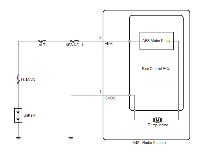
The ABS motor relay supplies power to the ABS pump motor. While the ABS is activated, the ECU turns the motor relay on and operates the ABS pump motor.
If the voltage supplied to the motor relay (+BM) is below the DTCs detection threshold due to low voltage from the battery or alternator, the DTC may be stored.
|
DTC Code |
DTC Detection Condition |
Trouble Area |
|---|---|---|
|
C0273/13 |
Any of the following is detected:
|
|
WIRING DIAGRAM
CAUTION / NOTICE / HINT
HINT:
When C1241/41 is output together with C0273/13, inspect and repair the trouble
areas indicated by C1241/41 first (See page .gif) ).
).
PROCEDURE
|
1. |
PERFORM ACTIVE TEST USING TECHSTREAM (ABS MOTOR RELAY) |
(a) Connect the Techstream to the DLC3.
(b) Start the engine.
(c) Select the Active Test on the Techstream (See page
).
ABS/VSC/TRAC
|
Tester Display |
Test Part |
Control Range |
Diagnostic Note |
|---|---|---|---|
|
Motor Relay |
ABS motor relay |
Relay ON/OFF |
Operating sound of motor can be heard |
(d) Check the operating sound of the ABS motor relay when operating it using the Techstream.
|
Result |
Proceed to |
|---|---|
|
The operating sound is heard |
A |
|
The operating sound is not heard |
B |
| B | .gif) |
GO TO STEP 3 |
|
.gif)
|
2. |
RECONFIRM DTC |
HINT:
This code is detected when a problem is identified in the brake actuator assembly.
The ABS motor relay is in the brake actuator assembly.
Therefore, ABS motor relay inspection and motor relay unit inspection cannot be performed. Be sure to check if the DTC is output before replacing the brake actuator assembly.
(a) Turn the ignition switch off.
(b) Clear the DTCs (See page ).
(c) Start the engine.
(d) Drive the vehicle at a speed of 20 km/h (12 mph) or more for 30 seconds or more.
Check if the same DTC is recorded (See page
).
|
Result |
Proceed to |
|---|---|
|
DTC (C0273/13) is not output |
A |
|
DTC (C0273/13) is output |
B |
HINT:
- If a speed signal of 15 km/h (9 mph) or more is input to the skid control ECU, with the ignition switch ON and the stop light switch off, the ECU performs self diagnosis of the motor and solenoid circuits.
- If the normal system code is output (the trouble code is not output), slightly jiggle the connectors, wire harness, and fuses of the brake actuator assembly. Make sure that no DTCs are output.
- If any DTCs are output while jiggling a connector or wire harness of the brake actuator assembly (skid control ECU), inspect and repair the connector or wire harness.
- It is suspected that the DTCs were output due to a bad connection of the connector terminal.
| A | |
CHECK FOR INTERMITTENT PROBLEMS |
| B | |
REPLACE BRAKE ACTUATOR ASSEMBLY |
|
3. |
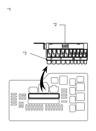
INSPECT ABS NO. 1 FUSE |
|
(a) Turn the ignition switch off. |
|
(b) Remove the fusible link block from the engine room relay block.
(c) Check if the fusible link is melted.
OK:
The fusible link is not melted.
(d) Measure the resistance according to the value(s) in the table below.
Standard Resistance:
|
Tester Connection |
Condition |
Specified Condition |
|---|---|---|
|
ABS NO. 1 (50 A) fuse - Body ground |
Always |
Below 1 Ω |
|
*1 |
Engine Room Relay Block |
|
*2 |
Fusible Link Block |
|
*3 |
ABS NO. 1 Fuse |
| NG | |
REPLACE FUSIBLE LINK BLOCK (ABS NO. 1 FUSE) |
|
|
4. |
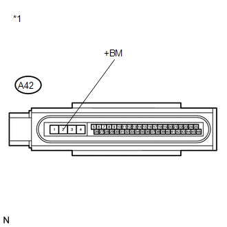
INSPECT SKID CONTROL ECU (+BM TERMINAL) |
|
(a) Install the fusible link block to the engine room relay block. |
|
(b) Make sure that there is no looseness at the locking part and the connecting part of the connector.
(c) Disconnect the skid control ECU connector.
(d) Measure the voltage according to the value(s) in the table below.
Standard Voltage:
|
Tester Connection |
Condition |
Specified Condition |
|---|---|---|
|
A42-2 (+BM) - Body ground |
Always |
11 to 14 V |
|
*1 |
Front view of wire harness connector (to Brake Actuator (Skid Control ECU)) |
| NG | |
REPAIR OR REPLACE HARNESS OR CONNECTOR (+BM CIRCUIT) |
|
|
5. |
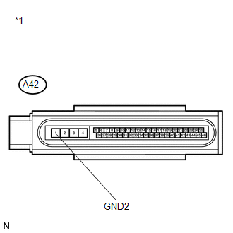
INSPECT SKID CONTROL ECU (GND2 TERMINAL) |
|
(a) Measure the resistance according to the value(s) in the table below. Standard Resistance:
|
|
| OK | |
REPLACE BRAKE ACTUATOR ASSEMBLY |
| NG | |
REPAIR OR REPLACE HARNESS OR CONNECTOR (GND2 CIRCUIT) |
 Open or Short Circuit in ABS Solenoid Relay Circuit (C0278/11)
DESCRIPTION
The ABS solenoid relay supplies power to the ABS solenoid and TRAC solenoid.
The solenoid relay is turned on 1.5 seconds after the ignition switch is turned
to ON, and is turned off if ...
 SFR Solenoid Circuit (C0226/21,C0236/22,C0246/23,C0256/24,C1225/25-C1228/28)
DESCRIPTION
These solenoids turn on when signals are received from the skid control ECU and
they control the pressure acting on the wheel cylinders to control the braking force.
DTC Cod ...
Other materials about Toyota Venza:
Dtc Check / Clear
DTC CHECK / CLEAR
1. CHECK DTC
(a) Connect the Techstream to the DLC3.
(b) Turn the engine switch on (IG).
(c) Turn the clearance sonar main switch on.
(d) Turn the Techstream on.
(e) Enter the following menus: Body Electrical / Intuitive P/A / DTC.
(f) ...
Seat belts
Make sure that all occupants are wearing their seat belts before driving the
vehicle.
- Correct use of the seat belts
1. Extend the shoulder belt so that it comes fully over the shoulder, but does
not come into contact with the neck or slide off ...
Reassembly
REASSEMBLY
CAUTION / NOTICE / HINT
HINT:
Perform "Inspection After Repair" after replacing the cylinder head sub-assembly
(See page ).
PROCEDURE
1. INSTALL SPARK PLUG TUBE
HINT:
When using a new cylinder head, the spark plug tubes must be r ...

0.117