Toyota Venza: Navigation Voice Circuit
DESCRIPTION
This circuit is used when the voice switch of the steering pad switch assembly is pushed.
Using this circuit, the navigation receiver assembly sends signals to the stereo component amplifier assembly.
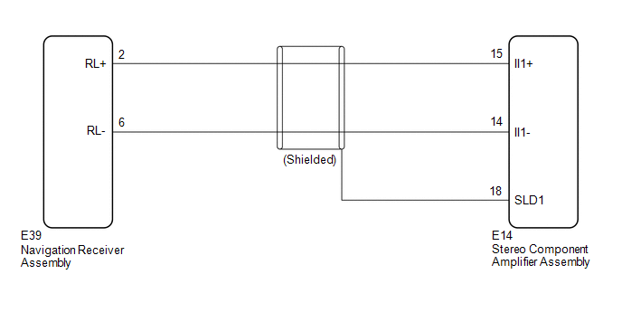
WIRING DIAGRAM
PROCEDURE
|
1. |
CHECK HARNESS AND CONNECTOR (NAVIGATION RECEIVER ASSEMBLY - STEREO COMPONENT AMPLIFIER ASSEMBLY) |
(a) Disconnect the E39 navigation receiver assembly connector.
(b) Disconnect the E14 stereo component amplifier assembly connector.
(c) Measure the resistance according to the value(s) in the table below.
Standard Resistance:
|
Tester connection |
Condition |
Specified condition |
|---|---|---|
|
E39-2 (RL+) - E14-15 (II1+) |
Always |
Below 1 Ω |
|
E39-6 (RL-) - E14-14 (II1-) |
Always |
Below 1 Ω |
|
E14-15 (II1+) - Body ground |
Always |
10 kΩ or higher |
|
E14-14 (II1-) - Body ground |
Always |
10 kΩ or higher |
|
E14-18 (SLD1) - Body ground |
Always |
10 kΩ or higher |
| OK | .gif) |
PROCEED TO NEXT SUSPECTED AREA SHOWN IN PROBLEM SYMPTOMS TABLE |
| NG | |
REPAIR OR REPLACE HARNESS OR CONNECTOR |
 AVC-LAN Circuit
DESCRIPTION
Each unit of the navigation system connected to the AVC-LAN (communication bus)
transmits switch signals via AVC-LAN communication.
If a short to +B or short to ground occurs in the AV ...
 Vehicle Speed Signal Circuit between Stereo Component Amplifier and Combination
Meter
Vehicle Speed Signal Circuit between Stereo Component Amplifier and Combination
Meter
DESCRIPTION
The stereo component amplifier assembly receives a vehicle speed signal from
the combination meter assembly to control the ASL function.
HINT:
A voltage of 12 V or 5 V is outp ...
Other materials about Toyota Venza:
Interior lights list
Your Toyota is equipped with the illuminated entry system to assist in entering
the vehicle. Due to the function of the system, the lights shown in the following
illustration automatically turn on/off according to the presence of the electronic
key (vehi ...
Ambient Temperature Sensor
Components
COMPONENTS
ILLUSTRATION
Inspection
INSPECTION
PROCEDURE
1. INSPECT AMBIENT TEMPERATURE SENSOR
(a) Measure the resistance according to the value(s) in the table below.
Standard Resistance:
Tester Connection
C ...
Tire size
- Typical tire size information
The illustration indicates typical tire size.
1. Tire use
(P = Passenger car, T = Temporary use)
2. Section width (millimeters)
3. Aspect ratio
(tire height to section width)
4. Tire construction code
(R = Radial ...

0.1695