Toyota Venza: Front Crankshaft Oil Seal
Components
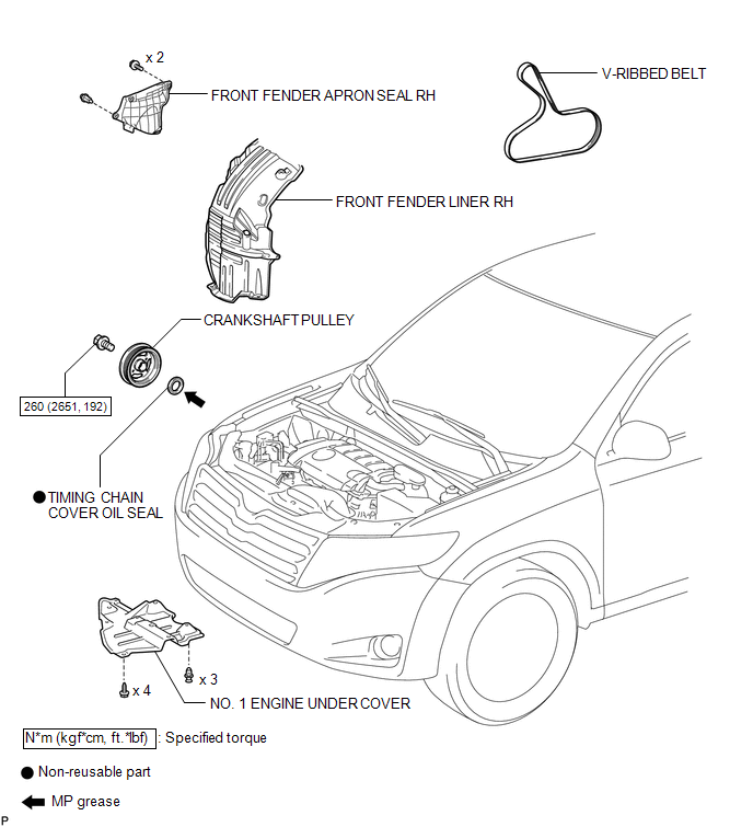
COMPONENTS
ILLUSTRATION
Removal
REMOVAL
PROCEDURE
1. REMOVE FRONT WHEEL RH
2. REMOVE NO. 1 ENGINE UNDER COVER
3. SEPARATE FRONT FENDER LINER RH
4. REMOVE FRONT FENDER APRON SEAL RH
.gif)
5. REMOVE V-RIBBED BELT
6. REMOVE CRANKSHAFT PULLEY
|
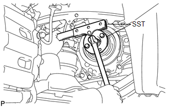
(a) Using SST, hold the crankshaft pulley and loosen the pulley bolt. Further loosen the bolt until 2 or 3 threads are screwed into the crankshaft. SST: 09213-54015 SST: 09330-00021 HINT: Part number of installation bolt for SST (crankshaft pulley holding tool): 91551-80650 (quantity: 2) |
|
|
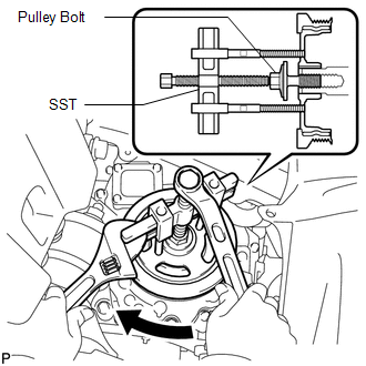
(b) Using SST and the pulley bolt, remove the crankshaft pulley. SST: 09950-50013 09951-05010 09952-05010 09953-05020 09954-05011 HINT: Apply a lubricant to the threads and end of SST. |
|
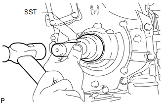
7. REMOVE TIMING CHAIN COVER OIL SEAL
|
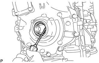
(a) Using a screwdriver, pry out the oil seal. HINT: Tape the screwdriver tip before use. NOTICE: Do not damage the surface of the oil seal press fit hole or the crankshaft. |
|
Installation
INSTALLATION
PROCEDURE
1. INSTALL TIMING CHAIN COVER OIL SEAL
(a) Apply MP grease to the lip of a new oil seal.
NOTICE:
- Do not allow foreign matter to contact the lip of the oil seal.
- Do not allow MP grease to contact the dust seal.
|
(b) Using SST and a hammer, tap in the oil seal until its surface is flush with the timing chain cover edge. SST: 09223-22010 NOTICE:
|
|
2. INSTALL CRANKSHAFT PULLEY
(a) Align the pulley set key with the key groove of the crankshaft pulley.
|
(b) Using SST, hold the crankshaft pulley and install the pulley bolt. SST: 09213-54015 SST: 09330-00021 Torque: 260 N·m {2651 kgf·cm, 192 ft·lbf} HINT: Part number of installation bolt for SST (crankshaft pulley holding tool): 91551-80650 (quantity: 2) |
|
.png)
3. INSTALL V-RIBBED BELT
.gif)
4. INSTALL FRONT FENDER APRON SEAL RH
5. INSTALL FRONT FENDER LINER RH
6. INSTALL NO. 1 ENGINE UNDER COVER
7. INSTALL FRONT WHEEL RH
Torque:
103 N·m {1050 kgf·cm, 76 ft·lbf}
 Reassembly
REASSEMBLY
PROCEDURE
1. INSTALL STIFFENING CRANKCASE RING PIN
NOTICE:
It is not necessary to remove the ring pin unless it is being replaced.
(a) Using a plastic-faced hammer, tap in 2 ...

Other materials about Toyota Venza:
Fail-safe Chart
FAIL-SAFE CHART
1. FAIL SAFE FUNCTION
(a) The following chart shows the status of the controls when the system is normal
and malfunctioning.
The passenger airbag ON/OFF indicator ("ON" and "OFF") comes on for
approximately 4 ...
Replacement
REPLACEMENT
PROCEDURE
1. REPLACE GENERATOR DRIVE END FRAME BEARING
(a) Remove the 4 screws and bearing retainer from the drive end frame.
(b) Using SST and a hammer, tap out the drive end ...
Theft Deterrent System Communication Line High Fixation (B279A)
DESCRIPTION
If the communication line (EFIO - IMI) to the certification ECU (smart key ECU
assembly) is stuck high output (e.g. shorted to +B), the ECM stores this DTC.
DTC No.
DTC Detection Condition
Trouble Area
...

0.1734