Toyota Venza: Lost Communication with Front Satellite Sensor Bus (B161A/8A)
DESCRIPTION
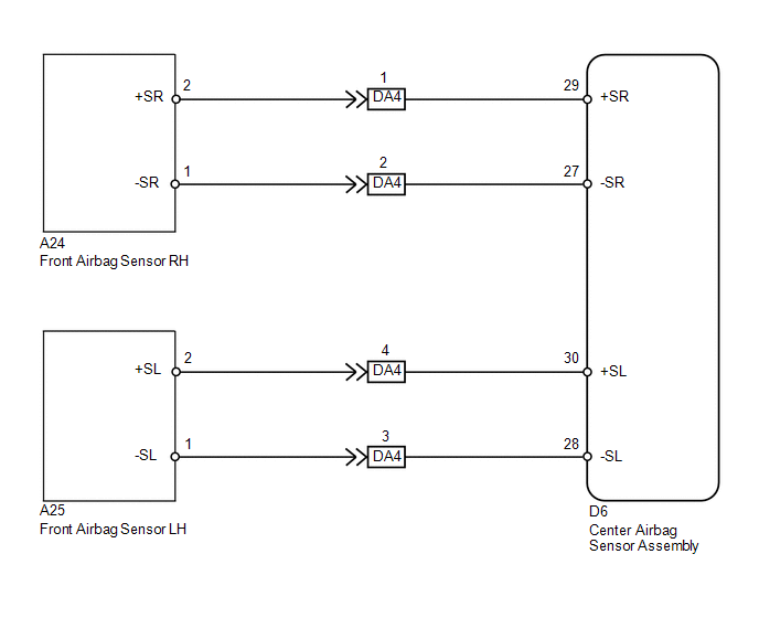
The front collision sensor circuit (front airbag sensor RH circuit and front airbag sensor LH circuit) is composed of the center airbag sensor assembly, front airbag sensor RH and front airbag sensor LH.
The front airbag sensor RH or front airbag sensor LH detect impacts to the vehicle and send signals to the center airbag sensor assembly to determine if the airbag should be deployed.
DTC B161A/8A is stored when a malfunction is detected in the front collision sensor circuit (front airbag sensor RH circuit and front airbag sensor LH circuit).
|
DTC No. |
DTC Detection Condition |
Trouble Area |
|---|---|---|
|
B161A/8A |
|
|
WIRING DIAGRAM
PROCEDURE
|
1. |
CHECK DTC |
(a) Turn the ignition switch to ON, and wait for at least 60 seconds.
(b) Turn the ignition switch off.
HINT:
If a communication error occurs, DTCs for both LH and RH sides will be stored simultaneously. To identify the malfunctioning area, turn the ignition switch off and then to ON again.
(c) Turn the ignition switch to ON, and wait for at least 60 seconds.
(d) Check for DTCs (See page .gif) ).
).
|
Result |
Proceed to |
|---|---|
|
DTCs B1613/83 and B1618/84 are not output. |
A |
|
DTC B1613/83 is output. |
B |
|
DTC B1618/84 is output. |
C |
HINT:
- DTCs indicating communication errors will be changed to DTCs indicating errors in initialization by turning the ignition switch off and then to ON again.
- Codes other than DTCs B1613/83 and B1618/84 may be output at this time, but they are not related to this check.
| B | .gif) |
GO TO DTC B1613/83 |
| C | |
GO TO DTC B1618/84 |
|
.gif)
|
2. |
CHECK CENTER AIRBAG SENSOR ASSEMBLY |
(a) Turn the ignition switch to ON, and wait for at least 60 seconds.
(b) Clear the DTCs stored in memory (See page
).
(c) Turn the ignition switch off.
(d) Turn the ignition switch to ON, and wait for at least 60 seconds.
(e) Check for DTCs (See page ).
OK:
DTC B161A/8A is not output.
HINT:
Codes other than DTC B161A/8A may be output at this time, but they are not related to this check.
| OK | |
USE SIMULATION METHOD TO CHECK |
| NG | |
REPLACE CENTER AIRBAG SENSOR ASSEMBLY |
 Rear Airbag Sensor RH Circuit Malfunction (B1630/23)
DESCRIPTION
The side collision sensor RH circuit (to determine deployment of the front seat
side airbag assembly RH and curtain shield airbag assembly RH) is composed of the
center airbag sensor ...
 Lost Communication with Front Airbag Sensor LH (B1617/84,B1618/84)
DESCRIPTION
The front airbag sensor LH circuit consists of the center airbag sensor assembly
and front airbag sensor LH.
The front airbag sensor LH detects impacts to the vehicle and sends signals ...
Other materials about Toyota Venza:
Front Passenger Side Door Entry Unlock Function does not Operate
DESCRIPTION
If the front passenger door entry lock function operates normally, but its entry
unlock function does not, this means that the request code from the front passenger
door is being output normally. In this case, a malfunction in the touch sensor ...
Terminals Of Ecu
TERMINALS OF ECU
1. CHECK POWER BACK DOOR ECU (POWER BACK DOOR MOTOR UNIT) (w/ POWER BACK DOOR
SYSTEM)
(a) Disconnect the L20 power back door ECU connector.
(b) Measure the voltage and resistance according to the value(s) in the table
below.
...
Engine compartment
► 2GR-FE engine
1. Engine coolant reservoir
2. Engine oil filler cap
3. Engine oil level dipstick
4. Brake fluid reservoir
5. Battery
6. Fuse box
7. Electric cooling fans
8. Condenser
9. Radiator
10.Washer fluid tank
► 1AR-FE engine
...

0.1565