Toyota Venza: Lost Communication with AFS LIN (B124D)
DESCRIPTION
The DTC is stored when the main body ECU (driver side junction block assembly) detects malfunctions in the LIN communication system.
|
DTC No. |
DTC Detection Condition |
Trouble Area |
|---|---|---|
|
B124D |
Malfunction in LIN communication system |
|
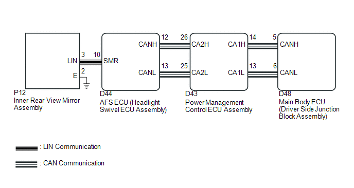
WIRING DIAGRAM
CAUTION / NOTICE / HINT
NOTICE:
First perform the communication function inspections in How to Proceed with Troubleshooting to confirm that there are no CAN communication malfunctions before troubleshooting this symptom.
PROCEDURE
|
1. |
CHECK FOR DTC |
(a) Clear the DTCs (See page .gif) ).
).
(b) Check for DTCs (See page ).
OK:
DTC B124D is not output.
| OK | .gif) |
USE SIMULATION METHOD TO CHECK |
|
.gif)
|
2. |
CHECK HARNESS AND CONNECTOR (AFS ECU - INNER REAR VIEW MIRROR ASSEMBLY) |
(a) Disconnect the D44 AFS ECU (headlight swivel ECU assembly) connector.
(b) Disconnect the P12 inner rear view mirror assembly connector.
(c) Measure the resistance according to the value(s) in the table below.
Standard Resistance:
|
Tester Connection |
Condition |
Specified Condition |
|---|---|---|
|
D44-10 (SMR) - P12-3 (LIN) |
Always |
Below 1 Ω |
|
P12-3 (LIN) - Body ground |
Always |
10 kΩ or higher |
| NG | |
REPAIR OR REPLACE HARNESS OR CONNECTOR |
|
|
3. |
INSPECT AFS ECU (HEADLIGHT SWIVEL ECU ASSEMBLY) |
(a) Reconnect the D44 AFS ECU (headlight swivel ECU assembly) connector.
|
(b) Connect an oscilloscope to the P12 inner rear view mirror assembly connector. |
|
.png)
|
(c) Check the waveform. OK:
|
|
.png)
| OK | |
REPLACE INNER REAR VIEW MIRROR ASSEMBLY |
| NG | |
REPLACE AFS ECU (HEADLIGHT SWIVEL ECU ASSEMBLY) |
 Automatic High Beam Camera (B124C)
DESCRIPTION
The DTC is stored when the main body ECU (driver side junction block assembly)
detects malfunctions in the camera (inner rear view mirror assembly).
DTC No.
DTC D ...
 Steering Position Sensor Malfunction (B2414)
DESCRIPTION
The AFS ECU (headlight swivel ECU assembly) receives signals indicating the swerve-angle
from the steering angle sensor using CAN communication.
DTC No.
DTC Detec ...
Other materials about Toyota Venza:
SRS Warning Light does not Come ON
DESCRIPTION
The SRS warning light is located on the combination meter assembly.
When the SRS is normal, the SRS warning light comes on for approximately 6 seconds
after the ignition switch is turned from off to ON, and then goes off automatically.
If ther ...
Control Module Performance (P0607)
MONITOR DESCRIPTION
The ECM continuously monitors its internal processors (CPUs) and heated oxygen
sensor transistors. This self-check ensures that the ECM is functioning properly.
DTC No.
DTC Detection Condition
Trouble Ar ...
Steering Lock Position Signal Circuit Malfunction (B2285)
DESCRIPTION
This DTC is stored when serial communication signals and LIN communication signals
in the circuit between the power management control ECU and steering lock actuator
assembly (steering lock ECU) are inconsistent.
DTC No.
...

0.1295