Toyota Venza: Key Reminder Buzzer does not Sound
DESCRIPTION
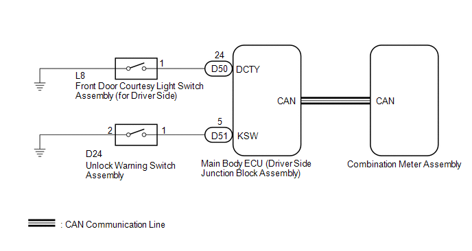
The key reminder warning buzzer sounds when the driver side door is opened while the ignition switch is in LOCK or ACC. The key reminder warning buzzer is activated when the main body ECU (driver side junction block assembly) sends an unlock warning switch signal and driver side door courtesy light switch signal to the combination meter assembly via CAN communication.
WIRING DIAGRAM
CAUTION / NOTICE / HINT
NOTICE:
Since the key reminder warning system has functions that use CAN communication,
first confirm that there is no malfunction in the communication system by inspecting
the CAN communication functions in accordance with the How to Proceed with Troubleshooting
procedure (See page .gif) ). Then, conduct the following
). Then, conduct the following
inspection procedure.
PROCEDURE
|
1. |
CHECK COMBINATION METER ASSEMBLY (BUZZER OPERATION) |
(a) Turn the ignition switch to ON. Place luggage on the passenger seat to cause the passenger seat belt warning light to blink.
(b) When driving the vehicle at 20 km/h (12 mph) or higher, check that the seat belt warning buzzer sounds to inform that the passenger seat belt is not fastened.
HINT:
The key reminder warning system sounds the buzzer built into the combination meter as a key reminder warning. This buzzer is also used for the seat belt warning system. Therefore, check the operation of the combination meter buzzer by checking if the buzzer sounds to inform that the seat belt is not fastened.
OK:
Combination meter buzzer sounds.
| NG | .gif) |
REPLACE COMBINATION METER ASSEMBLY |
|
.gif)
|
2. |
READ VALUE USING TECHSTREAM (DRIVER SIDE DOOR COURTESY LIGHT SWITCH) |
(a) Connect the Techstream to the DLC3.
(b) Turn the ignition switch to ON.
(c) Turn the Techstream on.
(d) Enter the following menus: Body Electrical / Main Body / Data List.
(e) Select D Door Courtesy SW in the Data List and read the Techstream display.
Main Body (Main Body ECU (Driver Side Junction Block Assembly))|
Tester Display |
Measurement Item/Range |
Normal Condition |
Diagnostic Note |
|---|---|---|---|
|
D Door Courtesy SW |
Driver side door courtesy light switch signal/ON or OFF |
ON: Driver side door open OFF: Driver side door closed |
- |
OK:
ON or OFF appears on the screen according to the driver side door condition.
| NG | |
GO TO STEP 4 |
|
|
3. |
READ VALUE USING TECHSTREAM (UNLOCK WARNING SWITCH) |
(a) Connect the Techstream to the DLC3.
(b) Turn the ignition switch to ON.
(c) Turn the Techstream on.
(d) Enter the following menus: Body Electrical / Main Body / Data List.
(e) Select Key Unlock Warning SW in the Data List and read the Techstream display.
Main Body (Main Body ECU (Driver Side Junction Block Assembly))|
Tester Display |
Measurement Item/Range |
Normal Condition |
Diagnostic Note |
|---|---|---|---|
|
Key Unlock Warning SW |
Unlock warning switch signal/ON or OFF |
ON: Key in ignition key cylinder OFF: No key in ignition key cylinder |
- |
OK:
ON or OFF appears on the screen according to whether the key is in the ignition key cylinder.
| OK | |
REPLACE MAIN BODY ECU (DRIVER SIDE JUNCTION BLOCK ASSEMBLY) |
| NG | |
GO TO STEP 6 |
|
4. |
INSPECT FRONT DOOR COURTESY LIGHT SWITCH ASSEMBLY (DRIVER SIDE) |
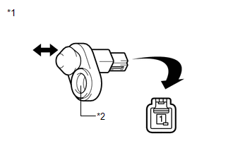
|
(a) Remove the front door courtesy light switch assembly (for driver
side) (See page |
|
(b) Measure the resistance according to the value(s) in the table below.
Standard Resistance:
|
Tester Connection |
Condition |
Specified Condition |
|---|---|---|
|
1 - Switch body |
Courtesy switch pushed (Door closed) |
10 kΩ or higher |
|
1 - Switch body |
Courtesy switch free (Door open) |
Below 1 Ω |
|
*1 |
Component without harness connected (Front Door Courtesy Light Switch Assembly (for Driver Side)) |
|
*2 |
Switch Body |
| NG | |
REPLACE FRONT DOOR COURTESY LIGHT SWITCH ASSEMBLY (DRIVER SIDE) |
|
|
5. |
CHECK HARNESS AND CONNECTOR (DRIVER SIDE DOOR COURTESY LIGHT SWITCH - MAIN BODY ECU) |
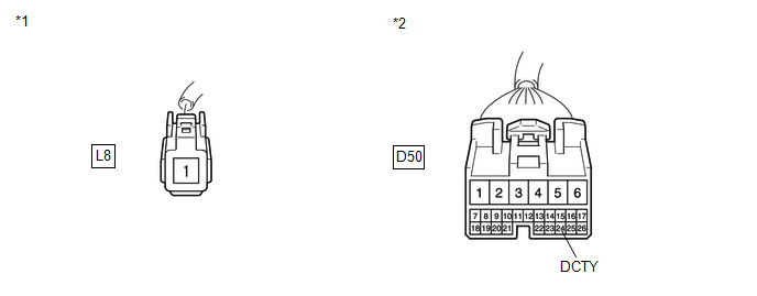
(a) Disconnect the D50 driver side junction block connector.
(b) Measure the resistance according to the value(s) in the table below.
Standard Resistance:
|
Tester Connection |
Condition |
Specified Condition |
|---|---|---|
|
L8-1 - D50-24 (DCTY) |
Always |
Below 1 Ω |
|
L8-1 - Body ground |
Always |
10 kΩ or higher |
|
*1 |
Front view of wire harness connector (to Front Door Courtesy Light Switch Assembly (for Driver Side)) |
|
*2 |
Front view of wire harness connector (to Main Body ECU (Driver Side Junction Block Assembly)) |
| OK | |
REPLACE MAIN BODY ECU (DRIVER SIDE JUNCTION BLOCK ASSEMBLY) |
| NG | |
REPAIR OR REPLACE HARNESS OR CONNECTOR |
|
6. |
INSPECT UNLOCK WARNING SWITCH ASSEMBLY |
|
(a) Remove the unlock warning switch assembly (See page
|
|
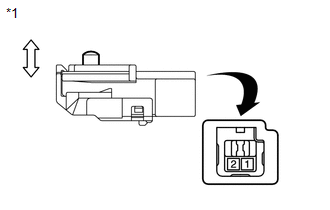
(b) Measure the resistance according to the value(s) in the table below.
Standard Resistance:
|
Tester Connection |
Condition |
Specified Condition |
|---|---|---|
|
1 - 2 |
Switch free (Key removed) |
10 kΩ or higher |
|
1 - 2 |
Switch pushed (Key set) |
Below 1 Ω |
|
*1 |
Component without harness connected (Unlock Warning Switch Assembly) |
| NG | |
REPLACE UNLOCK WARNING SWITCH ASSEMBLY |
|
|
7. |
CHECK HARNESS AND CONNECTOR (UNLOCK WARNING SWITCH - MAIN BODY ECU) |
(a) Disconnect the D51 driver side junction block connector.
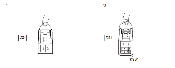
(b) Measure the resistance according to the value(s) in the table below.
Standard Resistance:
|
Tester Connection |
Condition |
Specified Condition |
|---|---|---|
|
D24-1 - D51-5 (KSW) |
Always |
Below 1 Ω |
|
D24-2 - Body ground |
Always |
Below 1 Ω |
|
D24-1 - Body ground |
Always |
10 kΩ or higher |
|
*1 |
Front view of wire harness connector (to Unlock Warning Switch Assembly) |
|
*2 |
Front view of wire harness connector (to Main Body ECU (Driver Side Junction Block Assembly)) |
| OK | |
REPLACE MAIN BODY ECU (DRIVER SIDE JUNCTION BLOCK ASSEMBLY) |
| NG | |
REPAIR OR REPLACE HARNESS OR CONNECTOR |
 Data List / Active Test
DATA LIST / ACTIVE TEST
1. DATA LIST
HINT:
Using the Techstream to read the Data List allows the values or states of switches,
sensors, actuators and other items to be read without removing any p ...

Other materials about Toyota Venza:
Diagnosis Circuit
DESCRIPTION
This circuit is used to read the DTCs that are output from the transponder key
ECU assembly with the Techstream.
WIRING DIAGRAM
CAUTION / NOTICE / HINT
NOTICE:
If the transponder key ECU assembly is replaced, register the key and ECU commu ...
How To Proceed With Troubleshooting
CAUTION / NOTICE / HINT
HINT:
Use the following procedure to troubleshoot.
PROCEDURE
1.
VEHICLE BROUGHT TO WORKSHOP
NEXT
2.
CUSTOMER PR ...
CD cannot be Ejected
PROCEDURE
1.
CHECK OPERATION
(a) Press the CD eject switch of the navigation receiver assembly for 10 seconds
or more and check that the CD is ejected.
OK:
CD is ejected.
NG
REPLACE NAVIGATION RECEIVER ...

0.1594