Toyota Venza: Installing child restraints using a seat belt (child restraint lock function belt)
- Rear-facing -- Infant seat/convertible seat
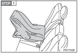
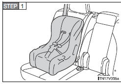
Place the child restraint system on the rear seat facing the rear of the vehicle.
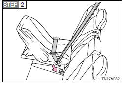
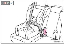
Run the seat belt through the child restraint system and insert the plate into the buckle. Make sure that the belt is not twisted.
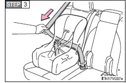
Fully extend the shoulder belt and then allow it to retract slightly in order to activate the ALR lock mode.
Lock mode allows the seat belt to retract only.
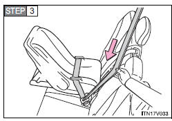
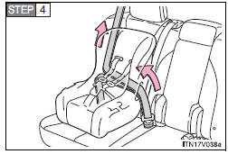
While pushing the child restraint system down into the rear seat, allow the shoulder belt to retract until the child restraint system is securely in place.
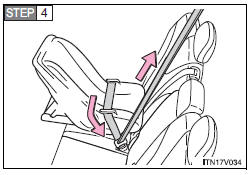
After the shoulder belt has retracted to a point where there is no slack in the belt, pull the belt to check that it cannot be extended.
- Forward-facing -- Convertible seat
Place the child restraint system on the seat facing the front of the vehicle.
Run the seat belt through the child restraint system and insert the plate into the buckle. Make sure that the belt is not twisted.
Fully extend the shoulder strap and then allow it to retract slightly into the ALR lock mode.
Lock mode allows the seat belt to retract only.
While pushing the child restraint system into the rear seat, allow the shoulder belt to retract until the child restraint system is securely in place.
After the shoulder belt has retracted to a point where there is no slack in the belt, pull the belt to check that it cannot be extended.

If the child restraint has a top tether strap, the top tether strap should be latched onto the top tether strap anchor.
- Booster seat
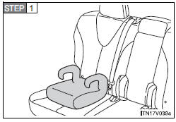
Place the booster seat on the seat facing the front of the vehicle.
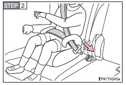
Sit the child in the booster seat.
Fit the seat belt to the booster seat according to the manufacturer’s instructions and insert the plate into the buckle. Make sure that the belt is not twisted.
Check that the shoulder belt is correctly positioned over the child’s shoulder, and that the lap belt is as low as possible.
 Installing child restraints
Follow the child restraint system manufacturer’s instructions. Firmly secure
child restraints to the rear seats using the LATCH anchors or a seat belt. Attach
the top tether strap when installin ...
 Removing a child restraint installed with a seat belt
Press the buckle release button and fully retract the seat belt. ...
Other materials about Toyota Venza:
Radio Antenna
Components
COMPONENTS
ILLUSTRATION
ILLUSTRATION
Installation
INSTALLATION
PROCEDURE
1. INSTALL RADIO ANTENNA ASSEMBLY
(a) Engage the 2 claws to install the radio antenna assembly.
(b) Place the antenna cord in the cutout of the ante ...
Malfunction in Deceleration Sensor (C0365/28,C1234/34,C1245/32,C1245/45)
DESCRIPTION
The skid control ECU receives signals from the yaw rate and acceleration sensor
via the CAN communication system.
The yaw rate sensor has a built-in acceleration sensor.
If there is trouble in the bus lines between the yaw rate and acceleratio ...
Monitor Drive Pattern
MONITOR DRIVE PATTERN
1. TEST MONITOR DRIVE PATTERN FOR ECT
CAUTION:
Perform this drive pattern on a level surface and strictly observe the posted
speed limits and traffic laws while driving.
HINT:
Performing this drive pattern is one method to simulate ...

0.1369