Toyota Venza: Installing child restraints
Follow the child restraint system manufacturer’s instructions. Firmly secure child restraints to the rear seats using the LATCH anchors or a seat belt. Attach the top tether strap when installing a child restraint.
The lap/shoulder belt can be used if your child restraint system is not compatible with the LATCH (Lower Anchors and Tethers for Children) system.
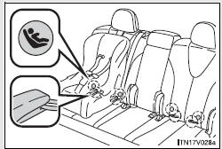
Child restraint LATCH anchors
LATCH anchors are provided for the outboard rear seats.
(Buttons displaying the location of the anchors are attached to the seats.)
Seat belts equipped with a child restraint locking mechanism (ALR/ELR belts except driver’s seat belt)
Anchor bracket (for top tether strap)
Anchor brackets are provided for all rear seats.
Installation with LATCH system
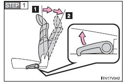
Fold the seatback while pulling the lever. Return the seatback and secure it as upright as possible (1st lock position). Adjust the seatback to the 3rd lock position.
1. 1st lock position
2. 3rd lock position
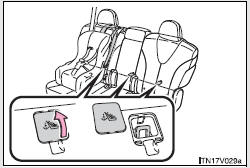
► Type A
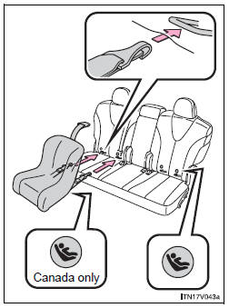
 Widen the gap between the seat cushion
and seatback slightly.
 Latch the hooks of the lower straps
onto the LATCH anchors.
The bars are installed in the clearance between the seat cushion and seatback.
 If the child restraint has a top
tether strap, the top tether strap should be latched onto the top tether strap anchor.
For owners in Canada:
The symbol on a child restraint system indicates the presence of a lower anchorage system.
►Type B
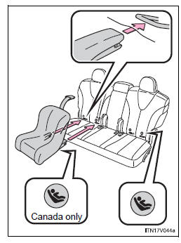
Widen the gap between the seat cushion
and seatback slightly.
Latch the buckles onto the LATCH
anchors.
The bars are installed in the clearance between the seat cushion and seatback.
If the child restraint has a top
tether strap, the top tether strap should be latched onto the top tether strap anchor.
For owners in Canada:
The symbol on a child restraint system indicates the presence of a lower anchorage system.
- Installing child restraints using a seat belt (child restraint lock function belt)
- Removing a child restraint installed with a seat belt
- Child restraint systems with a top tether strap
 Types of child restraints
Child restraint systems are classified into the following 3 types according to
the age and size of the child.
► Rear facing -- Infant seat/convertible
seat
► Forward facing -- Conv ...
 Installing child restraints using a seat belt (child restraint lock function
belt)
Installing child restraints using a seat belt (child restraint lock function
belt)
- Rear-facing -- Infant seat/convertible seat
Place the child restraint system on the rear seat facing the rear of the vehicle.
Run the seat belt through the child restraint system and ins ...
Other materials about Toyota Venza:
Installation
INSTALLATION
PROCEDURE
1. INSTALL WATER PUMP ASSEMBLY
(a) Install a new gasket and the water pump with the 7 bolts.
Torque:
21 N·m {214 kgf·cm, 15 ft·lbf}
2. INSTALL V-RIBBED BELT TENSIONE ...
System Diagram
SYSTEM DIAGRAM
Transmitting ECU
(Transmitter)
Receiving ECU
Signal
Communication Method
ECM
Power Steering ECU
Engine speed signal
Engine variation inform ...
Intake Manifold Runner Control Circuit Low (Bank 1) (P2009,P2010)
DESCRIPTION
The ECM activates the DC motor for the tumble control valve, which opens and
closes the tumble control valve. The ECM activates the DC motor based on engine
speed, coolant temperature, intake air temperature and other conditions.
D ...

0.1594