Toyota Venza: Removal
REMOVAL
PROCEDURE
1. DISCONNECT CABLE FROM NEGATIVE BATTERY TERMINAL
CAUTION:
Wait at least 90 seconds after disconnecting the cable from the negative (-)
battery terminal to disable the SRS system (See page
.gif) ).
).
NOTICE:
When disconnecting the cable, some systems need to be initialized after the cable
is reconnected (See page ).
2. REMOVE FRONT DOOR SCUFF PLATE
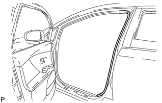
3. DISCONNECT FRONT DOOR OPENING TRIM WEATHERSTRIP
|
(a) Remove the rear part of the front door opening trim weatherstrip to the extent that allows removal of the lower center pillar garnish and center pillar garnish. |
|
4. REMOVE REAR DOOR SCUFF PLATE
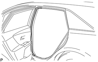
5. DISCONNECT REAR DOOR OPENING TRIM WEATHERSTRIP
|
(a) Remove the front part of the rear door opening trim weatherstrip to the extent that allows removal of the lower center pillar garnish and center pillar garnish. |
|
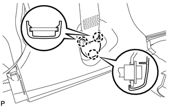
6. REMOVE LAP BELT OUTER ANCHOR COVER
|
(a) Disengage the 3 claws and remove the lap belt outer anchor cover. |
|
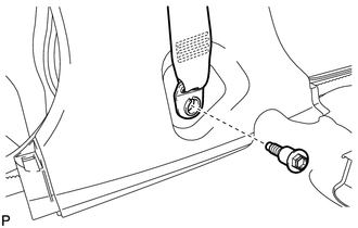
7. DISCONNECT FRONT SEAT OUTER BELT ASSEMBLY
|
(a) Remove the bolt and disconnect the floor end of the front seat outer belt assembly. |
|
8. REMOVE LOWER CENTER PILLAR GARNISH
9. REMOVE UPPER CENTER PILLAR GARNISH
10. REMOVE FRONT SEAT OUTER BELT ASSEMBLY
|
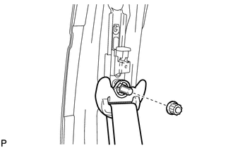
(a) Remove the nut and disconnect the shoulder anchor of the front seat outer belt assembly. |
|
|
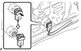
(b) Using a screwdriver, pull out the locking button in the direction shown by the arrow to release the lock, and disconnect the pretensioner connector as shown in the illustration. HINT: Tape the screwdriver tip before use. |
|
|
(c) Remove the bolt. |
|
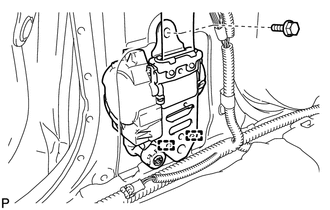
(d) Disengage the 2 guides and remove the front seat outer belt assembly.
11. REMOVE FRONT SHOULDER BELT ANCHOR ADJUSTER ASSEMBLY
|
(a) Remove the 2 bolts. |
|
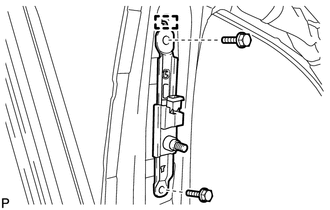
(b) Disengage the guide and remove the front shoulder belt anchor adjuster assembly.
 Precaution
PRECAUTION
CAUTION:
Replace any faulty seat belt components (outer belt, inner belt, bolts, nuts,
adjustable shoulder anchor, tether anchor hardware and other related parts). When
inspecting a v ...
 Inspection
INSPECTION
PROCEDURE
1. INSPECT FRONT SEAT OUTER BELT ASSEMBLY
NOTICE:
Do not disassemble the retractor.
(a) Before installing the front seat outer belt assembly, check the ELR.
(1) When the i ...
Other materials about Toyota Venza:
Panel Switches do not Function
PROCEDURE
1.
CHECK PANEL SWITCH
(a) Check for foreign matter around the switches that might prevent operation.
OK:
No foreign matter is found.
NG
REMOVE ANY FOREIGN MATTER FOUND
...
Pressure Control Solenoid "A" Performance (Shift Solenoid Valve SL1) (P0746)
SYSTEM DESCRIPTION
The TCM uses the vehicle speed signal and signals from the transmission speed
sensors (NC, NT) to detect the actual gear (1st, 2nd, 3rd, 4th, 5th or 6th gear).
Then the TCM compares the actual gear with the shift schedule in the TCM memo ...
Removal
REMOVAL
PROCEDURE
1. DISCONNECT CABLE FROM NEGATIVE BATTERY TERMINAL
NOTICE:
When disconnecting the cable, some systems need to be initialized after the cable
is reconnected (See page ).
2. REMOVE NO. 1 ENGINE COVER SUB-ASSEMBLY
3. REMOVE COOL AIR ...

0.1419