Toyota Venza: Charge Warning Light Comes ON while Driving
PROCEDURE
|
1. |
CHECK LOCK FUNCTION OF GENERATOR CLUTCH PULLEY |
(a) Check the lock function with the pulley installed in the vehicle.
(1) Visually check that the rotor in the generator operates with the engine running.
(b) Check the lock function with the pulley removed from the vehicle.
(1) Remove the generator pulley cap.
|
(2) Hold the generator rotor using SST, and turn the clutch pulley clockwise
to check that the outer ring locks (See page
Text in Illustration
OK: The outer ring locks. |
|
.gif) ).
).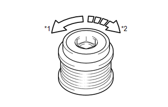
SST: 09820-63021
| NG | .gif) |
REPLACE GENERATOR CLUTCH PULLEY |
|
.gif)
|
2. |
CHECK INSTALLATION OF GENERATOR CLUTCH PULLEY |
(a) Start the engine and visually check the clutch pulley for looseness.
OK:
The clutch pulley is not loose.
| OK | |
REPLACE GENERATOR ASSEMBLY |
| NG | |
TIGHTEN GENERATOR CLUTCH PULLEY TO THE SPECIFIED TORQUE |
 Problem Symptoms Table
PROBLEM SYMPTOMS TABLE
Use the table below to help determine the cause of problem symptoms.
If multiple suspected areas are listed, the potential causes of the symptoms
are listed in o ...
 On-vehicle Inspection
ON-VEHICLE INSPECTION
PROCEDURE
1. CHECK BATTERY CONDITION
NOTICE:
If the battery is weak or if the engine is difficult to start, perform the following
procedure.
(a) Check the battery for dama ...
Other materials about Toyota Venza:
Dtc Check / Clear
DTC CHECK / CLEAR
NOTICE:
When the diagnosis system is changed from normal mode to check mode or vice versa,
all DTCs and freeze frame data recorded in normal mode are cleared. Before changing
modes, always check and make a note of DTCs and freeze frame ...
Engine Oil Cooler
Components
COMPONENTS
ILLUSTRATION
Removal
REMOVAL
PROCEDURE
1. REMOVE EXHAUST MANIFOLD ASSEMBLY
HINT:
See page
2. DRAIN ENGINE OIL
3. DRAIN ENGINE COOLANT
4. REMOVE OIL COOLER ASSEMBLY
(a) Remove the nut, union bolt, seal ...
Headlight Relay Circuit
DESCRIPTION
The main body ECU (driver side junction block assembly) controls the headlight
relays.
WIRING DIAGRAM
CAUTION / NOTICE / HINT
NOTICE:
Inspect the fuses for circuits related to this system before performing the following
inspection proc ...

0.1467