Toyota Venza: Installation
INSTALLATION
PROCEDURE
1. TEMPORARILY TIGHTEN REAR DISC BRAKE BLEEDER PLUG
(a) Temporarily tighten the rear disc brake bleeder plug.
HINT:
Fully tighten the rear disc brake bleeder plug after bleeding any air left in the system.
(b) Install the rear disc brake bleeder plug cap.
2. INSTALL REAR DISC
|
(a) Align the matchmarks of the rear disc and axle hub, and install the rear disc. Text in Illustration
NOTICE: When installing a new rear disc, select the installation position where the rear disc has minimal runout. |
|
.png)
3. INSTALL PARKING BRAKE SHOE ADJUSTING HOLE PLUG
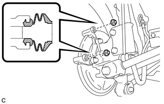
4. INSTALL REAR DISC BRAKE CYLINDER MOUNTING
|
(a) Install the rear disc brake cylinder mounting with the 2 bolts. Torque: 78 N·m {800 kgf·cm, 58 ft·lbf} |
|
.png)
5. INSTALL REAR DISC BRAKE BUSHING DUST BOOT
|
(a) Apply a light layer of lithium soap base glycol grease to the seal surfaces of 2 new rear disc brake bushing dust boots. HINT: Apply at least 0.3 g (0.01 oz.) of lithium soap base glycol grease to each rear disc brake bushing dust boot. |
|
.png)
|
(b) Install the 2 rear disc brake bushing dust boots to the rear disc brake cylinder mounting. |
|
6. INSTALL NO. 2 REAR DISC BRAKE CYLINDER SLIDE PIN
|
(a) Apply a light layer of lithium soap base glycol grease to the sliding part and the seal surface of the No. 2 rear disc brake cylinder slide pin. |
|
.png)
|
(b) Install the No. 2 rear disc brake cylinder slide pin to the rear disc brake cylinder mounting. |
|
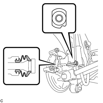
(c) Push the No. 2 rear disc brake cylinder slide pin into the rear disc brake bushing dust boot to align them.
7. INSTALL REAR DISC BRAKE CYLINDER SLIDE BUSHING
|
(a) Apply a light layer of lithium soap base glycol grease to the contact surface of the No. 1 rear disc brake cylinder slide pin. |
|
.png)
(b) Install a new rear disc brake cylinder slide bushing to the No. 1 rear disc brake cylinder slide pin.
8. INSTALL NO. 1 REAR DISC BRAKE CYLINDER SLIDE PIN
|
(a) Apply a light layer of lithium soap base glycol grease to the sliding part and the seal surface of the No. 1 rear disc brake cylinder slide pin. |
|
.png)
|
(b) Install the No. 1 rear disc brake cylinder slide pin to the rear disc brake cylinder mounting. |
|
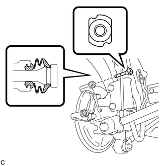
(c) Push the No. 1 rear disc brake cylinder slide pin into the rear disc brake bushing dust boot to align them.
9. INSTALL REAR DISC BRAKE PAD SUPPORT PLATE
|
(a) Install the 2 rear disc brake pad support plates to the rear disc brake cylinder mounting. NOTICE: Be sure to install the plates in the correct position and direction. |
|
.png)
10. INSTALL REAR ANTI-SQUEAL SHIM
(a) Install the rear anti-squeal shims to the 2 rear brake pads.
NOTICE:
- When replacing worn pads, the rear anti-squeal shims must be replaced together with the pads.
- Install the shims in the correct positions and directions.
11. INSTALL REAR DISC BRAKE PAD
|
(a) Install the 2 rear disc brake pads to the rear disc brake cylinder mounting. NOTICE:
|
|
.png)
12. INSTALL REAR DISC BRAKE CYLINDER ASSEMBLY
|
(a) Install the rear disc brake cylinder assembly to the rear disc brake cylinder mounting with the 2 bolts. Torque: 32 N·m {326 kgf·cm, 24 ft·lbf} |
|
.png)
13. CONNECT REAR FLEXIBLE HOSE
|
(a) Connect the rear flexible hose to the rear disc brake cylinder assembly with a new union bolt and a new gasket. Torque: 29 N·m {300 kgf·cm, 22 ft·lbf} HINT: Install the rear flexible hose lock securely into the lock hole in the rear disc brake cylinder assembly. |
|
.png)
14. FILL RESERVOIR WITH BRAKE FLUID
.gif)
15. BLEED BRAKE LINE
16. INSPECT FOR BRAKE FLUID LEAK
17. INSPECT FLUID LEVEL IN RESERVOIR
18. ADJUST PARKING BRAKE
19. INSTALL REAR WHEEL
Torque:
103 N·m {1050 kgf·cm, 76 ft·lbf}
 Inspection
INSPECTION
PROCEDURE
1. INSPECT PAD LINING THICKNESS
(a) Using a ruler, measure the pad lining thickness.
Text in Illustration
*1
Ruler
...
 Rear Brake Flexible Hose
Components
COMPONENTS
ILLUSTRATION
Removal
REMOVAL
CAUTION / NOTICE / HINT
NOTICE:
If both the left and right side hoses are removed at the same time, be sure to
place identification ma ...
Other materials about Toyota Venza:
Steering Angle Sensor Circuit Malfunction (C1231/31)
DESCRIPTION
The steering angle sensor signal is sent to the skid control ECU via the CAN
communication system. When there is a malfunction in the CAN communication system,
it will be detected by the steering angle sensor zero point malfunction diagnostic ...
Open in One Side of CAN Branch Line
DESCRIPTION
If some ECUs and sensors are not displayed on the "CAN Bus Check" screen of the
Techstream and some ECUs and sensors repeatedly appear and disappear from the screen
when the CAN main bus wires are normal (there is no open, short, sho ...
Inspection
INSPECTION
PROCEDURE
1. INSPECT TIRES
(a) Inspect the tires for wear and proper inflation pressure.
Cold Tire Inflation Pressure:
Tire Size
Front
kPa (kgf/cm2, psi)
Rear
kPa (kgf/cm2, psi)
P245/55R1 ...

0.2007