Toyota Venza: Installation
INSTALLATION
PROCEDURE
1. INSTALL REAR SEAT OUTER BELT ASSEMBLY
|
(a) Engage the 2 guides. |
|
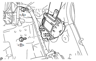
(b) Install the rear seat outer belt assembly with the 2 bolts.
Torque:
Bolt <A> :
7.5 N┬Ęm {77 kgf┬Ęcm, 66 in┬Ęlbf}
Bolt <B> :
42 N┬Ęm {428 kgf┬Ęcm, 31 ft┬Ęlbf}
|
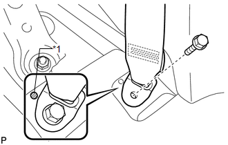
(c) Connect the shoulder anchor of the rear seat outer belt assembly with the bolt. Torque: 42 N┬Ęm {428 kgf┬Ęcm, 31 ft┬Ęlbf} |
|
.png)
(d) Check if the ELR locks.
NOTICE:
The check should be performed with the outer belt assembly installed.
(1) With the belt assembly installed, check that the belt locks when it is pulled out quickly.
2. INSTALL ROOF SIDE INNER GARNISH ASSEMBLY
.gif)
3. INSTALL DECK TRIM SIDE PANEL ASSEMBLY LH (for LH Side)
4. INSTALL DECK TRIM SIDE PANEL ASSEMBLY RH (for RH Side)
5. CONNECT REAR SEAT OUTER BELT ASSEMBLY
|
(a) Connect the floor anchor end of the rear seat outer belt assembly and install the bolt. Text in Illustration
Torque: 42 N┬Ęm {428 kgf┬Ęcm, 31 ft┬Ęlbf} NOTICE: Do not allow the anchor part of the rear seat outer belt assembly to overlap the protruding part of the floor panel. |
|
6. INSTALL LUGGAGE HOLD BELT STRIKER ASSEMBLY
7. INSTALL RECLINING REMOTE CONTROL BEZEL
8. INSTALL REAR SEAT ASSEMBLY LH (for LH Side)
9. CONNECT REAR SEAT NO. 2 RECLINING CONTROL CABLE SUB-ASSEMBLY (for LH Side)
10. INSTALL REAR SEAT OUTER TRACK BRACKET COVER (for LH Side)
11. INSTALL REAR SEAT INNER TRACK BRACKET COVER (for LH Side)
12. INSTALL REAR SEAT HEADREST ASSEMBLY (for LH Side)
13. INSTALL REAR SEAT ASSEMBLY RH (for RH Side)
14. CONNECT REAR SEAT RECLINING CONTROL CABLE SUB-ASSEMBLY (for RH Side)
15. INSTALL REAR SEAT OUTER TRACK BRACKET COVER (for RH Side)
16. INSTALL REAR SEAT INNER TRACK BRACKET COVER (for RH Side)
17. INSTALL REAR SEAT CENTER HEADREST ASSEMBLY (for RH Side)
18. INSTALL REAR SEAT HEADREST ASSEMBLY (for RH Side)
19. INSTALL REAR FLOOR FINISH PLATE
20. INSTALL REAR SEAT SUB FLOOR PANEL ASSEMBLY
21. INSTALL NO. 1 DECK BOARD
22. INSTALL DECK SIDE TRIM BOX LH
23. INSTALL NO. 3 DECK BOARD SUB-ASSEMBLY
24. INSTALL DECK SIDE TRIM BOX RH
25. INSTALL NO. 2 DECK BOARD SUB-ASSEMBLY
26. INSTALL DECK BOARD ASSEMBLY
27. INSTALL TONNEAU COVER ASSEMBLY (w/ Tonneau Cover)
28. CONNECT REAR DOOR OPENING TRIM WEATHERSTRIP
|
(a) Connect the rear door opening trim weatherstrip. |
|
.png)
29. INSTALL REAR DOOR SCUFF PLATE
 Removal
REMOVAL
PROCEDURE
1. REMOVE REAR DOOR SCUFF PLATE
2. DISCONNECT REAR DOOR OPENING TRIM WEATHERSTRIP
(a) Remove the rear part of the rear door opening trim weatherstrip to
the ext ...

Other materials about Toyota Venza:
Center Power Outlet Socket
Components
COMPONENTS
ILLUSTRATION
Installation
INSTALLATION
PROCEDURE
1. INSTALL CENTER POWER OUTLET SOCKET COVER
(a) Engage the 2 claws to install the center power outlet socket cover.
2 ...
Fuel Receiver Gauge Malfunction
DESCRIPTION
The meter CPU uses the fuel sender gauge assembly to determine the level
of the fuel in the fuel tank. The resistance of the fuel sender gauge will
vary between approximately 7.5 ╬® with the float at the full position, and
185 ╬ ...
Dtc Check / Clear
DTC CHECK / CLEAR
1. DTC CHECK USING TECHSTREAM
(a) Connect the Techstream to the DLC3.
(b) Turn the ignition switch to ON.
(c) Turn the Techstream on.
(d) Enter the following menus: Body / Air Conditioner / DTC.
(e) Check for DTCs.
2. DTC CLEAR USING T ...

0.1311