Toyota Venza: Installation
INSTALLATION
PROCEDURE
1. INSTALL REAR SEAT ASSEMBLY LH
(a) Place the rear seat assembly LH in the cabin.
NOTICE:
Be careful not to damage the vehicle body.
|
(b) Temporarily install the 2 bolts on the front side of the seat. |
|
.png)
|
(c) Temporarily install the 2 bolts on the rear side of the seat. |
|
.png)
(d) Install the rear seat assembly LH with the 4 bolts.
Torque:
37 N·m {377 kgf·cm, 27 ft·lbf}
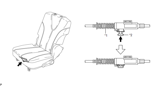
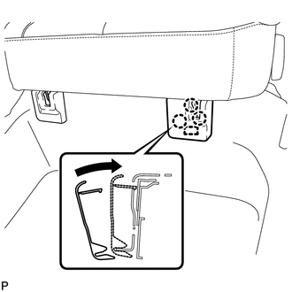
2. CONNECT REAR SEAT NO. 2 RECLINING CONTROL CABLE SUB-ASSEMBLY
(a) Remove the rear seat No. 2 reclining control cable from the carpet hole.
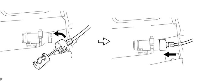
(b) Connect the rear seat No. 2 reclining control cable sub-assembly as shown in the illustration.
 Text in Illustration
|
*1 |
Protective Tape |
*2 |
Seat Track Adjusting Handle |
|
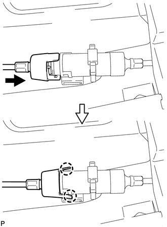
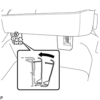
(c) Engage the 2 claws and connect the rear seat No. 2 reclining control cable sub-assembly as shown in the illustration. |
|
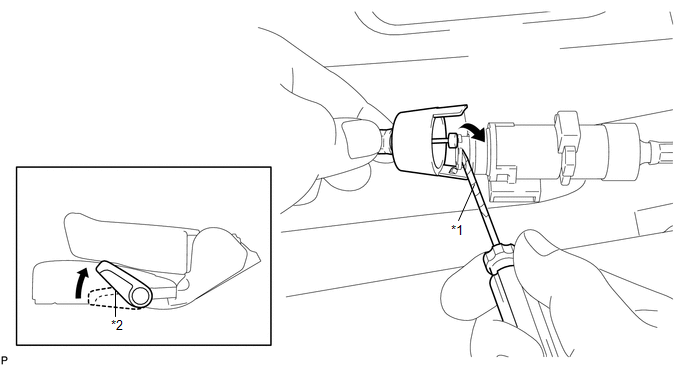
(d) Return the seatback to the upright position.
(e) Pull up the adjuster's lock piece to lock it as shown in the illustration.
 Text in Illustration
|
*1 |
Adjuster Spring |
*2 |
Lock Piece |
NOTICE:
When pressing the lock piece, make sure the adjuster's spring is not compressed.
3. INSTALL REAR SEAT OUTER TRACK BRACKET COVER
|
(a) Engage the guide and 3 claws and install the rear seat outer track bracket cover as shown in the illustration. |
|
4. INSTALL REAR SEAT INNER TRACK BRACKET COVER
|
(a) Engage the guide and 3 claws and install the rear seat inner track bracket cover as shown in the illustration. |
|
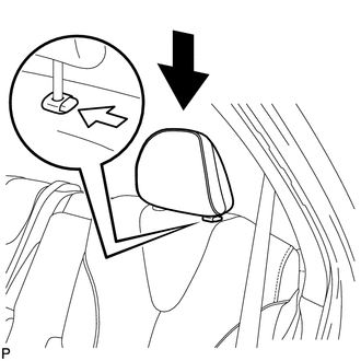
5. INSTALL REAR SEAT HEADREST ASSEMBLY
|
(a) Install the rear seat headrest assembly as shown in the illustration. |
|
 Disassembly
DISASSEMBLY
PROCEDURE
1. REMOVE SEAT ADJUSTER COVER CAP LH
(a) Using a screwdriver wrapped with protective tape, disengage the 3
claws and remove the seat adjuster cover cap LH.
T ...

Other materials about Toyota Venza:
Registration
REGISTRATION
CAUTION / NOTICE / HINT
NOTICE:
When the automatic transaxle is replaced, the transaxle compensation
code must be input into the TCM (proceed to Procedure 1). After the automatic
transaxle is reinstalled, the Quick Response (QR) ...
Fog light switch
The fog lights improve visibility in difficult driving conditions, such as
in rain or fog. The fog lights can be used when the headlights are on low beam.
Type A
1. Off
2. On
Type B
1. Off
2. On
Wiper intervals can be adjusted for intermittent ...
Charge Warning Light Comes ON while Driving
PROCEDURE
1.
CHECK LOCK FUNCTION OF GENERATOR CLUTCH PULLEY
(a) Check the lock function with the pulley installed in the vehicle.
(1) Visually check that the rotor in the generator operates with the engine running.
(b) Check ...

0.1791