Toyota Venza: Installation
INSTALLATION
PROCEDURE
1. INSTALL FRONT SEAT ASSEMBLY
(a) Place the front seat assembly in the cabin.
NOTICE:
Be careful not to damage the vehicle body.
(b) Connect each connector under the front seat assembly.
(c) Connect the cable to the negative (-) battery terminal.
NOTICE:
When disconnecting the cable, some systems need to be initialized after the cable
is reconnected (See page .gif) ).
).
(d) Temporarily install the front seat assembly with the 4 bolts.
(e) Operate the slide and vertical power seat switch knob and move the seat to the rearmost position.
|
(f) Tighten the 2 bolts on the front side of the front seat assembly. Torque: 37 N·m {377 kgf·cm, 27 ft·lbf} HINT: Tighten the bolts in the order shown in the illustration. |
|
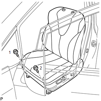
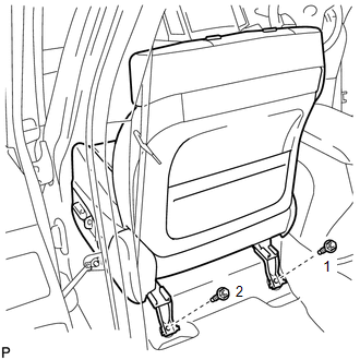
(g) Operate the slide and vertical power seat switch knob and move the front seat assembly to the foremost position.
|
(h) Tighten the 2 bolts on the rear side of the front seat assembly. Torque: 37 N·m {377 kgf·cm, 27 ft·lbf} HINT: Tighten the bolts in the order shown in the illustration. |
|
2. INSTALL FRONT SEAT REAR INNER TRACK COVER
|
(a) Engage the 2 claws to install the front seat rear inner track cover. |
|
.png)
3. INSTALL FRONT SEAT REAR OUTER TRACK COVER
|
(a) Engage the 2 claws to install the front seat rear outer track cover. |
|
.png)
4. INSTALL FRONT SEAT HEADREST ASSEMBLY
5. INSPECT FRONT SEAT ASSEMBLY
(a) Inspect the power seat operation.
(b) w/ Seat Heater System:
Check the seat heater operation.
(1) Turn the ignition switch to ON.
(2) Turn the seat heater switch on.
(3) Wait 5 minutes or more and confirm that the seat surface becomes warm.
6. INSPECT SRS WARNING LIGHT
(See page )
 Reassembly
REASSEMBLY
PROCEDURE
1. INSTALL FRONT SEAT WIRE RH (for Front Passenger Side)
(a) Engage each clamp and install the front seat wire RH.
2. INSTALL OCCUPANT CLASSIFICATION ECU (for Front Passenger ...

Other materials about Toyota Venza:
Using a flat bed truck
If you use chains or cables to tie down your vehicle, the angles shaded in black
must be 45°.
Do not overly tighten the tie downs or the vehicle may be damaged.
NOTICE
- To prevent body damage when towing a sling-type truck
Do not tow with a sli ...
System Diagram
SYSTEM DIAGRAM
Communication Table
Sender
Receiver
Signal
Line
Main body ECU (Driver side junction block assembly)
Sliding roof ECU (Sliding roof drive gear sub-assembly)
Key ...
Transmission Fluid Pressure Sensor / Switch "E" Circuit Low (P0989,P0990)
DESCRIPTION
ATF pressure switch No. 3 is installed in the lock-up solenoid ATF output passage
and is used to detect a malfunction in the lock-up solenoid.
DTC No.
DTC Detection Condition
Trouble Area
P0989
...

0.164