Toyota Venza: Engine Coolant Temperature Circuit Malfunction (P0115,P0117,P0118)
DESCRIPTION
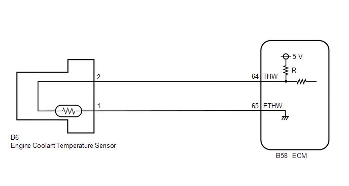
A thermistor, whose resistance value varies according to the engine coolant temperature, is built into the engine coolant temperature sensor.
The structure of the sensor and its connection to the ECM are similar to those of the intake air temperature sensor.
HINT:
When any of DTCs P0115, P0117 or P0118 are set, the ECM enters fail-safe mode. During fail-safe mode, the engine coolant temperature is estimated to be 80°C (176°F) by the ECM. Fail-safe mode continues until a pass condition is detected.
|
DTC No. |
DTC Detection Condition |
Trouble Area |
|---|---|---|
|
P0115 |
An open or short in engine coolant temperature sensor circuit for 0.5 seconds (1 trip detection logic) |
|
|
P0117 |
A short in engine coolant temperature sensor circuit for 0.5 seconds (1 trip detection logic) |
|
|
P0118 |
An open in engine coolant temperature sensor circuit for 0.5 seconds (1 trip detection logic) |
|
HINT:
When any of these DTCs are set, check the engine coolant temperature by entering the following menus on the Techstream: Powertrain / Engine / Data List / Coolant Temp.
|
Temperature Displayed |
Malfunction |
|---|---|
|
-40°C (-40°F) |
Open circuit |
|
Higher than 135°C (275°F) |
Short circuit |
MONITOR DESCRIPTION
- The engine coolant temperature sensor is used to monitor the engine
coolant temperature. The engine coolant temperature sensor has a thermistor
with a resistance that varies according to the temperature of the engine
coolant. When the coolant temperature is low, the resistance in the thermistor
increases. When the temperature is high, the resistance drops. These variations
in resistance are reflected in the output voltage from the sensor. The ECM
monitors the sensor voltage and uses this value to calculate the engine
coolant temperature. When the sensor output voltage deviates from the normal
operating range, the ECM interprets this as a malfunction in the engine
coolant temperature sensor and sets a DTC.
- Example:
- If the sensor output voltage is more than 4.91 V for 0.5 seconds or more, the ECM determines that there is an open in the engine coolant temperature sensor circuit, and sets DTC P0118. Conversely, if the voltage output is less than 0.14 V for 0.5 seconds or more, the ECM determines that there is a short in the sensor circuit, and sets DTC P0117.
- Example:
MONITOR STRATEGY
|
Related DTCs |
P0115: Engine Coolant Temperature Sensor Range Check (Chattering) P0117: Engine Coolant Temperature Sensor Range Check (Low voltage) P0118: Engine Coolant Temperature Sensor Range Check (High voltage) |
|
Required Sensors/Components (Main) |
Engine coolant temperature sensor |
|
Required Sensors/Components (Sub) |
- |
|
Frequency of Operation |
Continuous |
|
Duration |
0.5 seconds |
|
MIL Operation |
Immediate |
|
Sequence of Operation |
None |
TYPICAL ENABLING CONDITIONS
|
Monitor runs whenever the following DTCs are not stored |
None |
TYPICAL MALFUNCTION THRESHOLDS
P0115|
Engine coolant temperature sensor voltage [Engine coolant temperature] |
Less than 0.14 V, or higher than 4.91 V [Higher than 135°C (275°F), or less than -60°C (-76°F)] |
|
Engine coolant temperature sensor voltage [Engine coolant temperature] |
Less than 0.14 V [Higher than 135°C (275°F)] |
|
Engine coolant temperature sensor voltage [Engine coolant temperature] |
Higher than 4.91 V [Below -60°C (-76°F)] |
COMPONENT OPERATING RANGE
|
Engine coolant temperature sensor voltage [Engine coolant temperature] |
0.14 to 4.91 V [-60 to 135°C (-76 to 275°F)] |
CONFIRMATION DRIVING PATTERN
- Connect the Techstream to the DLC3.
- Turn the ignition switch to ON and turn the Techstream on.
- Clear the DTCs (even if no DTCs are stored, perform the Clear DTC procedure)
(See page
.gif) ).
). - Turn the ignition switch off and wait for at least 30 seconds.
- Turn the ignition switch to ON and turn the Techstream on.
- Wait 0.5 seconds or more.
- Enter the following menus: Powertrain / Engine / Trouble Codes.
- Read the Pending DTCs.
HINT:
- If a pending DTC is output, the system is malfunctioning.
- If a pending DTC is not output, perform the following procedure.
- Enter the following menus: Powertrain / Engine / Utility / All Readiness.
- Input the DTC: P0115, P0117 or P0118.
- Check the DTC judgment result.
Techstream Display
Description
NORMAL
- DTC judgment completed
- System normal
ABNORMAL
- DTC judgment completed
- System abnormal
INCOMPLETE
- DTC judgment not completed
- Perform driving pattern after confirming DTC enabling conditions
N/A
- Unable to perform DTC judgment
- Number of DTCs which do not fulfill DTC preconditions has reached ECU's memory limit
HINT:
- If the judgment result shows NORMAL, the system is normal.
- If the judgment result shows ABNORMAL, the system has a malfunction.
- If the test result is INCOMPLETE or N/A and no pending DTC is output,
perform a universal trip and check for permanent DTCs (See page
).
HINT:
- If a permanent DTC is output, the system is malfunctioning.
- If no permanent DTC is output, the system is normal.
WIRING DIAGRAM
CAUTION / NOTICE / HINT
HINT:
- Read freeze frame data using the Techstream. The ECM records vehicle and driving condition information as freeze frame data the moment a DTC is stored. When troubleshooting, freeze frame data can help determine if the vehicle was moving or stationary, if the engine was warmed up or not, if the air fuel ratio was lean or rich, and other data from the time the malfunction occurred
- If DTC P0117 is stored, check that the engine does not overheat (the DTC P0117 may be stored due to engine overheating).
PROCEDURE
|
1. |
READ VALUE USING TECHSTREAM (COOLANT TEMP) |
(a) Connect the Techstream to the DLC3.
(b) Turn the ignition switch to ON.
(c) Turn the Techstream on.
(d) Enter the following menus: Powertrain / Engine / Data List / Coolant Temp.
(e) Read the value displayed on the Techstream.
OK:
Between 75 and 100°C (167 and 212°F) with warm engine.
|
Result |
Proceed to |
|---|---|
|
-40°C (-40°F) |
A |
|
Higher than 135°C (275°F) |
B |
|
Between 75 and 100°C (167 and 212°F) |
C |
HINT:
- If there is an open circuit, the Techstream indicates -40°C (-40°F).
- If there is a short circuit, the Techstream indicates higher than 135°C (275°F).
| B | .gif) |
GO TO STEP 4 |
| C | |
CHECK FOR INTERMITTENT PROBLEMS |
|
.gif)
|
2. |
READ VALUE USING TECHSTREAM (CHECK FOR OPEN IN WIRE HARNESS) |
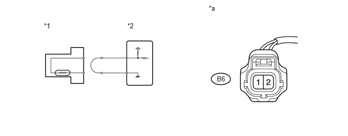
(a) Confirm good connection at the engine coolant temperature sensor connector.
 Text in Illustration
|
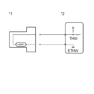
*1 |
Engine Coolant Temperature Sensor |
*2 |
ECM |
|
*a |
Front view of wire harness connector (to Engine Coolant Temperature Sensor) |
- |
- |
(b) Disconnect the engine coolant temperature sensor connector.
(c) Connect terminals 1 and 2 of the engine coolant temperature sensor connector on the wire harness side.
(d) Connect the Techstream to the DLC3.
(e) Turn the ignition switch to ON.
(f) Turn the Techstream on.
(g) Enter the following menus: Powertrain / Engine / Data List / Coolant Temp.
(h) Read the value displayed on the Techstream.
Standard:
Higher than 135°C (275°F)
HINT:
Perform "Inspection After Repair" after replacing the engine coolant temperature
sensor (See page ).
| OK | |
REPLACE ENGINE COOLANT TEMPERATURE SENSOR |
|
|
3. |
CHECK HARNESS AND CONNECTOR (ENGINE COOLANT TEMPERATURE SENSOR - ECM) |
(a) Disconnect the engine coolant temperature sensor connector.
(b) Disconnect the ECM connector.
(c) Measure the resistance according to the value(s) in the table below.
Standard Resistance (Check for Open):
|
Tester Connection |
Condition |
Specified Condition |
|---|---|---|
|
B6-2 - B58-64 (THW) |
Always |
Below 1 Ω |
|
B6-1 - B58-65 (ETHW) |
Always |
Below 1 Ω |
| OK | |
REPLACE ECM |
| NG | |
REPAIR OR REPLACE HARNESS OR CONNECTOR (ENGINE COOLANT TEMPERATURE SENSOR - ECM) |
|
4. |
READ VALUE USING TECHSTREAM (CHECK FOR SHORT IN WIRE HARNESS) |
|
(a) Disconnect the engine coolant temperature sensor connector. Text in Illustration
|
|
(b) Connect the Techstream to the DLC3.
(c) Turn the ignition switch to ON.
(d) Turn the Techstream on.
(e) Enter the following menus: Powertrain / Engine / Data List / Coolant Temp.
(f) Read the value displayed on the Techstream.
Standard:
-40°C (-40°F)
HINT:
Perform "Inspection After Repair" after replacing the engine coolant temperature
sensor (See page ).
| OK | |
REPLACE ENGINE COOLANT TEMPERATURE SENSOR |
|
|
5. |
CHECK HARNESS AND CONNECTOR (ENGINE COOLANT TEMPERATURE SENSOR - ECM) |
(a) Disconnect the engine coolant temperature sensor connector.
(b) Disconnect the ECM connector.
(c) Measure the resistance according to the value(s) in the table below.
Standard Resistance (Check for Short):
|
Tester Connection |
Condition |
Specified Condition |
|---|---|---|
|
B6-2 or B58-64 (THW) - Body ground |
Always |
10 kΩ or higher |
| OK | |
REPLACE ECM |
| NG | |
REPAIR OR REPLACE HARNESS OR CONNECTOR (ENGINE COOLANT TEMPERATURE SENSOR - ECM) |
 Intake Air Temperature Circuit Low Input (P0112,P0113)
DESCRIPTION
The intake air temperature sensor, in the mass air flow meter, monitors
the intake air temperature. The intake air temperature sensor has a built-in
thermistor with a res ...
 Engine Coolant Temperature Circuit Range / Performance Problem (P0116)
DESCRIPTION
Refer to DTC P0115 (See page ).
DTC No.
DTC Detection Condition
Trouble Area
P0116
When either of the following conditions i ...
Other materials about Toyota Venza:
Removal
REMOVAL
CAUTION / NOTICE / HINT
HINT:
Use the same procedure for the LH side and RH side.
The following procedure listed below is for the LH side.
PROCEDURE
1. REMOVE FRONT WHEEL
2. REMOVE FRONT WIPER ARM HEAD CAP
3. REMOVE FRONT WI ...
How To Proceed With Troubleshooting
CAUTION / NOTICE / HINT
HINT:
Use the following procedure to troubleshoot the cruise control system.
*: Use the Techstream.
PROCEDURE
1.
VEHICLE BROUGHT TO WORKSHOP
NEXT
...
Portable Player cannot be Registered
CAUTION / NOTICE / HINT
HINT:
Some versions of "Bluetooth" compatible audio players may not function properly,
or the functions may be limited using the navigation receiver assembly, even if
the portable audio player itself can play files (See ...

0.1623