Toyota Venza: Inspection
INSPECTION
PROCEDURE
1. INSPECT BRAKE DISC INSIDE DIAMETER
|
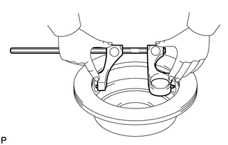
(a) Using a brake drum gauge or an equivalent tool, measure the inside diameter of the disc. Standard inside diameter of a new disc: 190 mm (7.48 in.) Maximum inside diameter: 191 mm (7.52 in.) If the inside diameter is more than the maximum, replace the rear disc. |
|
2. INSPECT PARKING BRAKE SHOE LINING THICKNESS
|
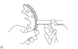
(a) Using a ruler, measure the thickness of the parking brake shoe lining. Standard thickness: 2.45 mm (0.0965 in.) Minimum thickness: 1.0 mm (0.0394 in.) If the lining thickness is less than the minimum, or if there is severe or uneven wear, replace the parking brake shoe assembly. NOTICE: Always replace both the right and left parking brake shoes together. |
|
3. INSPECT BRAKE DISC AND PARKING BRAKE SHOE LINING FOR PROPER CONTACT
|
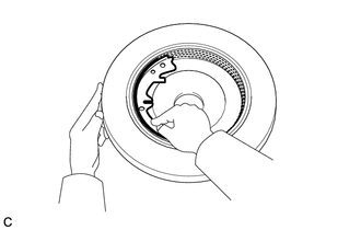
(a) Apply chalk to the inside surface of the disc, then grind down the brake shoe lining to fit the disc. If the contact between the disc and the brake shoe lining is incorrect, repair it using a brake shoe grinder or replace the parking brake shoe assembly. NOTICE: Always replace both the right and left parking brake shoes together. |
|
 Disassembly
DISASSEMBLY
CAUTION / NOTICE / HINT
HINT:
Use the same procedure for the RH side and the LH side.
The procedure listed below is for the LH side.
PROCEDURE
1. REMOVE REAR WHEEL
...
 Reassembly
REASSEMBLY
CAUTION / NOTICE / HINT
NOTICE:
Before installation, apply high temperature grease to the parts indicated by
arrows (See page ).
PROCEDURE
1. INSTALL NO. 2 PARKING BRAKE SHOE HOLD D ...
Other materials about Toyota Venza:
Removal
REMOVAL
PROCEDURE
1. REMOVE FRONT SEAT HEADREST ASSEMBLY
2. REMOVE FRONT SEAT REAR OUTER TRACK COVER
3. REMOVE FRONT SEAT REAR INNER TRACK COVER
4. REMOVE FRONT SEAT ASSEMBLY
5. REMOVE RECLINING POWER SEAT SWITCH KNOB
6. REMOVE SLIDE AND VER ...
Tire Pressure Warning Ecu
Components
COMPONENTS
ILLUSTRATION
ILLUSTRATION
Removal
REMOVAL
CAUTION / NOTICE / HINT
NOTICE:
Before removing the tire pressure warning ECU, read the registered transmitter
IDs of all wheels and write them down to use for re-registration of ...
Rear Sensor Communication Malfunction (C1AED)
DESCRIPTION
This DTC is stored when there is an open or short circuit in the communication
line between the rear sensors and the ECU, or when there is a malfunction in a rear
sensor.
DTC No.
DTC Detection Condition
Troubl ...

0.1171