Toyota Venza: Disassembly
DISASSEMBLY
CAUTION / NOTICE / HINT
HINT:
- Use the same procedure for the RH side and the LH side.
- The procedure listed below is for the LH side.
PROCEDURE
1. REMOVE REAR WHEEL
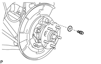
2. REMOVE REAR AXLE SHAFT NUT (for AWD)
NOTICE:
Perform this procedure only when the No. 1 parking brake shoe hold down spring pin is replaced.
HINT:
See page .gif) .
.
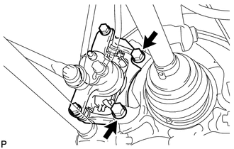
3. SEPARATE REAR DISC BRAKE CALIPER ASSEMBLY
|
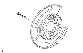
(a) Remove the 2 bolts and rear disc brake caliper assembly. NOTICE:
|
|
4. REMOVE REAR DISC
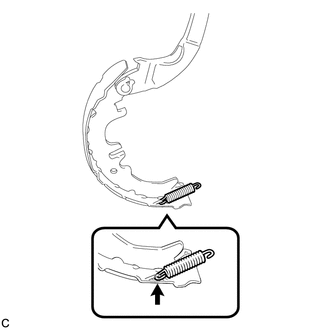
5. REMOVE NO. 1 PARKING BRAKE SHOE RETURN TENSION SPRING
|
(a) Remove the 2 No. 1 parking brake shoe return tension springs. |
|

6. SEPARATE NO. 1 PARKING BRAKE SHOE ASSEMBLY
|
(a) Remove the No. 1 parking brake shoe hold down spring cup, parking brake shoe hold down spring and No. 2 parking brake shoe hold down spring cup, and separate the No. 1 parking brake shoe assembly from the backing plate. |
|
7. REMOVE PARKING BRAKE SHOE STRUT
|
(a) Remove the parking brake shoe strut and the parking brake shoe strut compression spring. |
|
8. SEPARATE NO. 2 PARKING BRAKE SHOE ASSEMBLY
|
(a) Remove the No. 1 parking brake shoe hold down spring cup, parking brake shoe hold down spring and No. 2 parking brake shoe hold down spring cup, and separate the No. 2 parking brake shoe assembly from the backing plate. |
|
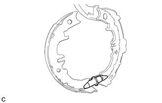
9. REMOVE PARKING BRAKE SHOE ADJUSTING SCREW SET
|
(a) Remove the parking brake shoe adjusting screw set. |
|
10. REMOVE NO. 1 PARKING BRAKE SHOE ASSEMBLY
|
(a) Separate the No. 2 parking brake shoe return tension spring and remove the No. 1 parking brake shoe assembly. |
|
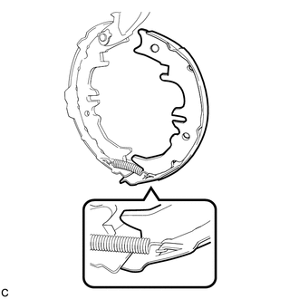
11. REMOVE NO. 2 PARKING BRAKE SHOE RETURN TENSION SPRING
|
(a) Remove the No. 2 parking brake shoe return tension spring from the No. 2 parking brake shoe assembly. |
|
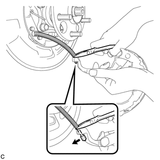
12. REMOVE NO. 2 PARKING BRAKE SHOE ASSEMBLY WITH PARKING BRAKE SHOE LEVER
|
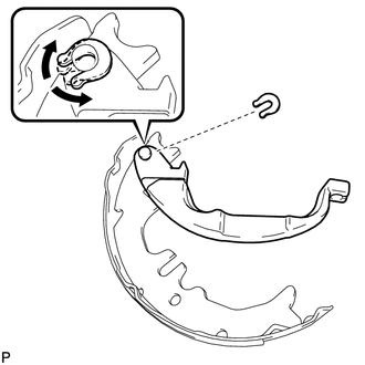
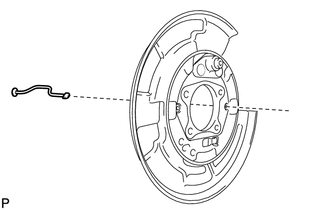
(a) Using needle-nose pliers, separate the No. 3 parking brake cable assembly from the parking brake shoe lever as shown in the illustration. NOTICE: Be careful not to damage the No. 3 parking brake cable assembly. |
|
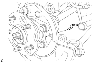
13. REMOVE PARKING BRAKE SHOE LEVER
|
(a) Remove the C-washer, shim and the parking brake shoe lever from the No. 2 parking brake shoe assembly. HINT: The shim is installed only when a clearance adjustment between the parking brake lever and parking brake shoe C-washer is necessary. Therefore, some models may have no shim. |
|
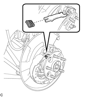
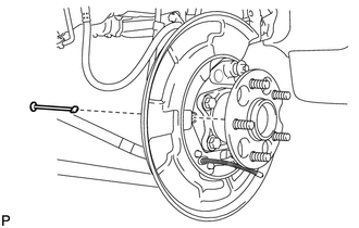
14. REMOVE PARKING BRAKE SHOE GUIDE PLATE SET BOLT
|
(a) Remove the parking brake shoe guide plate set bolt and the parking brake shoe guide plate. |
|
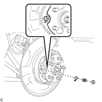
15. REMOVE NO. 1 PARKING BRAKE SHOE HOLD DOWN SPRING PIN (for 2WD)
|
(a) Remove the No. 1 parking brake shoe hold down spring pin. |
|
16. REMOVE NO. 2 PARKING BRAKE SHOE HOLD DOWN SPRING PIN (for AWD)
|
(a) Remove the No. 2 parking brake shoe hold down spring pin. |
|
17. REMOVE REAR AXLE HUB AND BEARING ASSEMBLY (for 2WD)
NOTICE:
Perform this procedure only when the No. 2 parking brake shoe hold down spring pin is replaced.
HINT:
See page .
18. REMOVE REAR AXLE HUB AND BEARING ASSEMBLY (for AWD)
NOTICE:
Perform this procedure only when the No. 1 parking brake shoe hold down spring pin is replaced.
HINT:
See page .
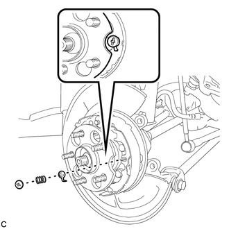
19. REMOVE NO. 2 PARKING BRAKE SHOE HOLD DOWN SPRING PIN (for 2WD)
|
(a) Remove the No. 2 parking brake shoe hold down spring pin. |
|
20. REMOVE NO. 1 PARKING BRAKE SHOE HOLD DOWN SPRING PIN (for AWD)
|
(a) Remove the No. 1 parking brake shoe hold down spring pin. |
|
 Components
COMPONENTS
ILLUSTRATION
ILLUSTRATION
ILLUSTRATION
ILLUSTRATION
ILLUSTRATION
ILLUSTRATION
ILLUSTRATION
...
 Inspection
INSPECTION
PROCEDURE
1. INSPECT BRAKE DISC INSIDE DIAMETER
(a) Using a brake drum gauge or an equivalent tool, measure the inside
diameter of the disc.
Standard inside diameter of ...
Other materials about Toyota Venza:
Components
COMPONENTS
ILLUSTRATION
ILLUSTRATION
ILLUSTRATION
ILLUSTRATION
ILLUSTRATION
ILLUSTRATION
ILLUSTRATION
ILLUSTRATION
ILLUSTRATION
ILLUSTRATION
ILLUSTRATION
...
System Diagram
SYSTEM DIAGRAM
Communication Table
Transmitting ECU
(Transmitter)
Receiving ECU
(Receiver)
Signal
Communication Method
Combination meter
Power management control ECU
...
Diagnostic Trouble Code Chart
DIAGNOSTIC TROUBLE CODE CHART
HINT:
Parameters listed in the chart may not be exactly the same as your readings due
to the type of instrument or other factors. If a trouble code is displayed during
the DTC check, inspect the trouble areas listed for that ...

0.1308