Toyota Venza: Accessory Meter
Components
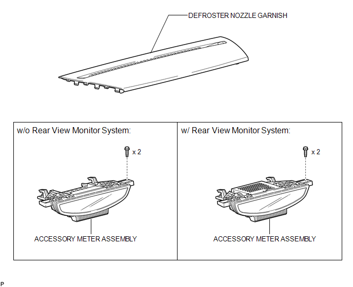
COMPONENTS
ILLUSTRATION
Installation
INSTALLATION
PROCEDURE
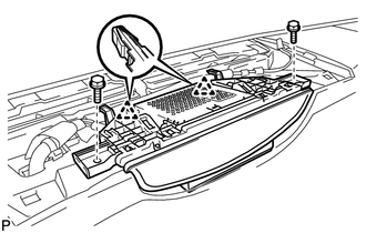
1. INSTALL ACCESSORY METER ASSEMBLY (w/o Rear View Monitor System)
|
(a) Connect the connector. |
|
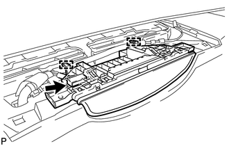
(b) Engage the 2 clamps.
|
(c) Engage the 2 clips. |
|
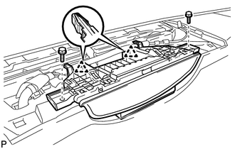
(d) Install the accessory meter assembly with the 2 bolts.
2. INSTALL ACCESSORY METER ASSEMBLY (w/ Rear View Monitor System)
|
(a) Connect the connectors. |
|
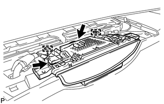
(b) Engage the 2 clamps.
|
(c) Engage the 2 clips. |
|
(d) Install the accessory meter assembly with the 2 bolts.
3. INSTALL DEFROSTER NOZZLE GARNISH
.gif)
Removal
REMOVAL
PROCEDURE
1. REMOVE DEFROSTER NOZZLE GARNISH
.gif)
2. REMOVE ACCESSORY METER ASSEMBLY (w/o Rear View Monitor System)
|
(a) Remove the 2 bolts. |
|
.png)
(b) Disengage the 2 clips.
|
(c) Disengage the 2 clamps. |
|
.png)
(d) Disconnect the connector and remove the accessory meter assembly.
3. REMOVE ACCESSORY METER ASSEMBLY (w/ Rear View Monitor System)
|
(a) Remove the 2 bolts. |
|
.png)
(b) Disengage the 2 clips.
|
(c) Disengage the 2 clamps. |
|
.png)
(d) Disconnect the connectors and remove the accessory meter assembly.

 Clock System
...
Other materials about Toyota Venza:
Installation
INSTALLATION
PROCEDURE
1. INSTALL FRONT DRIVE SHAFT ASSEMBLY LH
(a) Align the splines of the shaft and install the drive shaft assembly
LH using a brass bar and a hammer.
NOTICE:
Set the shaft snap ring with the opening fac ...
Torque Sensor Zero Point Adjustment Undone (C1515,C1525)
DESCRIPTION
These DTCs do not indicate a malfunction. The power steering ECU stores these
DTCs when it determines that the rotation angle sensor value initialization and
torque sensor zero point calibration have not been performed.
DTC No.
...
How To Proceed With Troubleshooting
CAUTION / NOTICE / HINT
HINT:
Use the following procedure to troubleshoot the key reminder warning
system.
*: Use the Techstream.
PROCEDURE
1.
VEHICLE BROUGHT TO WORKSHOP
NEXT
...

0.1287