Toyota Venza: Inspection
INSPECTION
PROCEDURE
1. INSPECT REAR DOOR LOCK ASSEMBLY LH
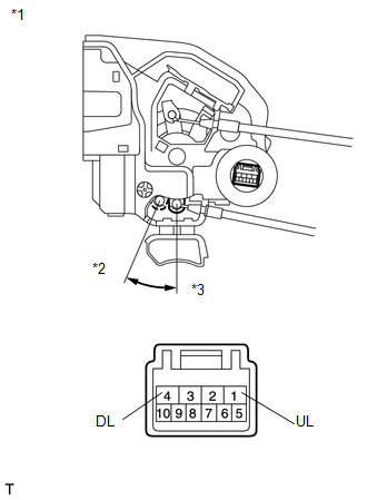
(a) Check the operation of the door lock motor.
|
(1) Apply battery voltage and check the operation of the door lock motor. OK:
If the result is not as specified, replace the rear door lock assembly LH. |
|
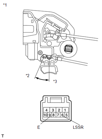
(b) Check the operation of the unlock detection switch.
|
(1) Measure the resistance according to the value(s) in the table below. Standard Resistance:
If the result is not as specified, replace the rear door lock assembly LH. |
|
2. INSPECT REAR DOOR LOCK ASSEMBLY RH
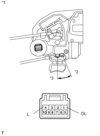
(a) Check the operation of the door lock motor.
|
(1) Apply battery voltage and check the operation of the door lock motor. OK:
If the result is not as specified, replace the rear door lock assembly RH. |
|
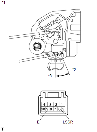
(b) Check the operation of the unlock detection switch.
|
(1) Measure the resistance according to the value(s) in the table below. Standard Resistance:
If the result is not as specified, replace the rear door lock assembly RH. |
|
 Removal
REMOVAL
PROCEDURE
1. DISCONNECT CABLE FROM NEGATIVE BATTERY TERMINAL
CAUTION:
Wait at least 90 seconds after disconnecting the cable from the negative (-)
battery terminal to disable the SRS sys ...
 Installation
INSTALLATION
PROCEDURE
1. INSTALL REAR DOOR LOCK ASSEMBLY
NOTICE:
When reusing the removed rear door lock assembly, replace the door lock
wiring harness seal on the connector with a ne ...
Other materials about Toyota Venza:
Installation
INSTALLATION
PROCEDURE
1. INSTALL NO. 1 FUEL TANK CUSHION
(a) Install 8 new No. 1 fuel tank cushions to the fuel tank.
2. INSTALL FUEL MAIN TUBE SUPPORT
(a) Install the fuel main tube su ...
Installation
INSTALLATION
PROCEDURE
1. INSTALL PARKING BRAKE PEDAL ASSEMBLY
(a) Install the parking brake pedal assembly with the 3 nuts.
Torque:
21 N·m {214 kgf·cm, 15 ft·lbf}
(b) Connect t ...
Power Management Control Ecu
Components
COMPONENTS
ILLUSTRATION
Removal
REMOVAL
PROCEDURE
1. REMOVE FRONT DOOR SCUFF PLATE RH
2. REMOVE COWL SIDE TRIM SUB-ASSEMBLY RH
3. REMOVE NO. 2 INSTRUMENT PANEL UNDER COVER SUB-ASSEMBLY
4. REMOVE LOWER INSTRUMENT PANEL SUB-ASS ...

0.1227