Toyota Venza: Inspection
INSPECTION
PROCEDURE
1. INSPECT PRELOAD
|
(a) Secure the steering column assembly in a vise. Text in Illustration
NOTICE: When using a vise, do not overtighten it. |
|
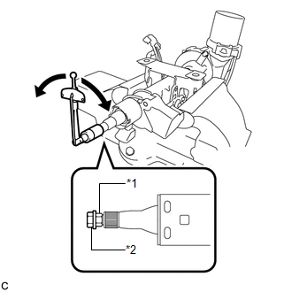
(b) Install a service nut to the steering main shaft.
Recommended service nut:
Thread diameter
12.0 mm (0.472 in.)
Thread pitch
1.25 mm (0.0492 in.)
(c) Install the steering wheel assembly set nut to the steering main shaft.
(d) Lock the steering wheel assembly set nut using the service nut.
(e) Using a torque wrench, turn the main shaft and measure the preload.
Torque:
Preload :
0.98-1.58 N·m {10-16 kgf·cm, 9-13 in·lbf}
If the preload is not as specified, replace the steering column assembly.
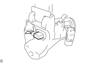
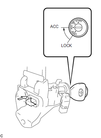
2. INSPECT STEERING LOCK OPERATION (w/o Smart Key System)
|
(a) Check that the steering lock mechanism is activated when the key is removed. |
|
|
(b) Check that the steering lock mechanism is deactivated when the key is inserted and turned to the ACC position. HINT: If there is any abnormality, replace the ignition switch lock cylinder assembly or steering column upper bracket assembly. |
|
 Disassembly
DISASSEMBLY
CAUTION / NOTICE / HINT
NOTICE:
When using a vise, do not overtighten it.
PROCEDURE
1. REMOVE STEERING LOCK ACTUATOR ASSEMBLY (w/ Smart Key System)
(a) Secure the steering column ass ...
 Reassembly
REASSEMBLY
CAUTION / NOTICE / HINT
NOTICE:
When using a vise, do not overtighten it.
PROCEDURE
1. INSTALL STEERING LOCK ACTUATOR ASSEMBLY (w/ Smart Key System)
(a) Secure the steering column ass ...
Other materials about Toyota Venza:
Front Speed Sensor RH Circuit (C0200/31,C0205/32,C1271/71,C1272/72,C1330/35,C1331/36)
DESCRIPTION
The speed sensor detects wheel speed and sends the appropriate signals to the
skid control ECU. These signals are used for the ABS control system.
Speed sensor rotors have 48 serrations. The hall IC type speed sensor use the
frequency of outp ...
Cursor or Map Rotates when Vehicle Stopped
PROCEDURE
1.
CHECK CONDITION
(a) Check with the customer if the vehicle has been turned by a turntable.
OK:
Vehicle has not been turned by a turntable.
HINT:
If the vehicle is turned on a turntable with ...
Transmission Range Sensor Circuit Malfunction (PRNDL Input) (P0705)
DESCRIPTION
The park/neutral position switch assembly detects the shift lever position and
sends signals to the ECM.
DTC No.
DTC Detection Condition
Trouble Area
P0705
One of the following condit ...

0.1276