Toyota Venza: Front Passenger Side Door Entry Lock Function does not Operate
DESCRIPTION
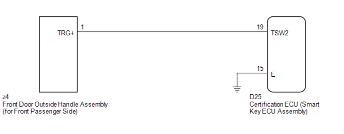
If the front passenger door entry unlock function operates normally, but its entry lock function does not, this means that the request code from the front passenger door is being output normally. In this case, a malfunction in the lock sensor circuit (from the certification ECU (smart key ECU assembly) to the front door outside handle assembly (lock sensor)) is suspected.
WIRING DIAGRAM
CAUTION / NOTICE / HINT
NOTICE:
- The smart key system (for entry function) uses a multiplex communication
system (LIN communication system) and CAN communication system. Inspect
the communication function by following How to Proceed with Troubleshooting
(See page
.gif) ). Troubleshoot the smart
). Troubleshoot the smart
key system (for entry function) after confirming that the communication system is functioning properly. - Confirm that another key is not in the cabin.
PROCEDURE
|
1. |
CHECK POWER DOOR LOCK OPERATION |
(a) When the door control switch on the master switch assembly is operated, check
that the doors unlock and lock according to switch operation (See page
).
OK:
Door locks operate normally.
| NG | .gif) |
GO TO POWER DOOR LOCK CONTROL SYSTEM (Proceed to Problem Symptoms Table) |
|
.gif)
|
2. |
READ VALUE USING TECHSTREAM (DOOR LOCK POSITION SWITCH) |
(a) Connect the Techstream to the DLC3.
(b) Turn the engine switch on (IG).
(c) Turn the Techstream on.
(d) Enter the following menus: Body Electrical / Main Body / Data List.
(e) Read the Data List according to the display on the Techstream.
Main Body (Main Body ECU (Driver Side junction Block Assembly))|
Tester Display |
Measurement Item/Range |
Normal Condition |
Diagnostic Note |
|---|---|---|---|
|
P-Door Lock Pos SW |
Front passenger side door lock position switch signal/ON or OFF |
ON: Front passenger side door is unlocked OFF: Front passenger side door is locked |
- |
OK:
On the Techstream screen, the display changes between ON and OFF as shown in the chart above.
| NG | |
GO TO LIGHTING SYSTEM (Proceed to Door Unlock Detection Switch Circuit) |
|
|
3. |
READ VALUE USING TECHSTREAM (DOOR OUTSIDE HANDLE) |
(a) Enter the following menus: Body Electrical / Smart Key / Data List.
(b) Read the Data List according to the display on the Techstream.
Smart Key (Certification ECU (Smart Key ECU Assembly))|
Tester Display |
Measurement Item/Range |
Normal Condition |
Diagnostic Note |
|---|---|---|---|
|
P-Door Trigger SW |
Front passenger side door lock switch / ON or OFF |
ON: Entry lock switch pressed OFF: Entry lock switch not pressed |
- |
OK:
On the Techstream screen, the display changes between ON and OFF as shown in the chart above.
| OK | |
REPLACE CERTIFICATION ECU (SMART KEY ECU ASSEMBLY) |
|
|
4. |
CHECK HARNESS AND CONNECTOR (FRONT DOOR OUTSIDE HANDLE - CERTIFICATION ECU) |
(a) Disconnect the certification ECU (smart key ECU assembly) connector.
|
(b) Disconnect the front door outside handle assembly (for front passenger side) connector. |
|
(c) Measure the resistance according to the value(s) in the table below.
Standard Resistance:
|
Tester Connection |
Condition |
Specified Condition |
|---|---|---|
|
D25-19 (TSW2) - z4-1 (TRG+) |
Always |
Below 1 Ω |
|
D25-19 (TSW2) - Body ground |
Always |
10 kΩ or higher |
|
z4-1 (TRG+) - Body ground |
Always |
10 kΩ or higher |
|
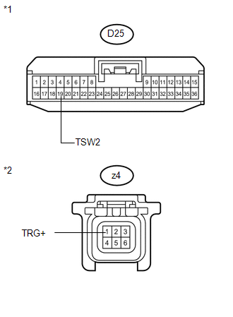
*1 |
Front view of wire harness connector (to Certification ECU (Smart Key ECU Assembly)) |
|
*2 |
Front view of wire harness connector (to Front Door Outside Handle Assembly (for Front Passenger Side)) |
| NG | |
REPAIR OR REPLACE HARNESS OR CONNECTOR |
|
|
5. |
INSPECT CERTIFICATION ECU (SMART KEY ECU ASSEMBLY) (LOCK SENSOR SIGNAL INPUT) |
(a) Reconnect the certification ECU (smart key ECU assembly) connector.
(b) Reconnect the front door outside handle assembly (for front passenger side) connector.
(c) Measure the voltage and check for pulses according to the value(s) in the table below.
Standard:
|
Tester Connection |
Condition |
Specified Condition |
|---|---|---|
|
D25-19 (TSW2) - D25-15 (E) |
|
Pulse generation |
|
D25-19 (TSW2) - D25-15 (E) |
|
Below 2 V |
|
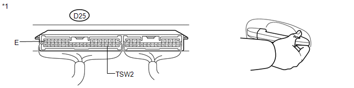
*1 |
Component with harness connected (Certification ECU (Smart Key ECU Assembly)) |
| OK | |
REPLACE CERTIFICATION ECU (SMART KEY ECU ASSEMBLY) |
| NG | |
REPLACE FRONT DOOR OUTSIDE HANDLE ASSEMBLY (for Front Passenger Side) |
 Driver Side Door Entry Lock Function does not Operate
DESCRIPTION
If the driver door entry unlock function operates normally, but its entry lock
function does not, this means that the request code from the driver door is being
output normally. In th ...
 Room Oscillator does not Recognize Key
DESCRIPTION
If the room oscillator does not recognize a key, one of the following may be
the cause: 1) communication between the indoor electrical key oscillator (for front
floor) and key cannot ...
Other materials about Toyota Venza:
Camshaft Position "A" - Timing Over-Advanced or System Performance (Bank 1)
(P0011,P0012)
DESCRIPTION
Refer to DTC P0010 (See page ).
DTC No.
DTC Detection Condition
Trouble Area
P0011
The valve timing is stuck at a certain value when in the advance range
(1 trip detection logic).
...
Removal
REMOVAL
PROCEDURE
1. REMOVE NO. 1 ENGINE COVER SUB-ASSEMBLY
2. REMOVE CAMSHAFT TIMING OIL CONTROL VALVE ASSEMBLY (for Exhaust Side)
(a) Disconnect the oil control valve connector.
(b) Remove the ...
Data Signal Circuit between Navigation Receiver Assembly and Stereo Jack Adapter
DESCRIPTION
The No. 1 stereo jack adapter assembly sends the sound data signal or image data
signal from a USB device to the navigation receiver assembly via this circuit.
WIRING DIAGRAM
PROCEDURE
1.
CHECK HARNESS AND CONNECTOR ( ...

0.1677