Toyota Venza: Driver Side Door Entry Lock Function does not Operate
DESCRIPTION
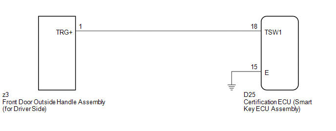
If the driver door entry unlock function operates normally, but its entry lock function does not, this means that the request code from the driver door is being output normally. In this case, a malfunction in the lock sensor circuit (from the certification ECU (smart key ECU assembly) to the front door outside handle assembly (lock sensor)) is suspected.
WIRING DIAGRAM
CAUTION / NOTICE / HINT
NOTICE:
- The smart key system (for entry function) uses a multiplex communication
system (LIN communication system) and CAN communication system. Inspect
the communication function by following How to Proceed with Troubleshooting
(See page
.gif) ). Troubleshoot the smart
). Troubleshoot the smart
key system (for entry function) after confirming that the communication system is functioning properly. - Confirm that another key is not in the cabin.
PROCEDURE
|
1. |
CHECK POWER DOOR LOCK OPERATION |
(a) When the door control switch on the master switch assembly is operated, check
that the doors unlock and lock according to switch operation (See page
).
OK:
Door locks operate normally.
| NG | .gif) |
GO TO POWER DOOR LOCK CONTROL SYSTEM (Proceed to Problem Symptoms Table) |
|
.gif)
|
2. |
READ VALUE USING TECHSTREAM (DOOR LOCK POSITION SWITCH) |
(a) Connect the Techstream to the DLC3.
(b) Turn the engine switch on (IG).
(c) Turn the Techstream on.
(d) Enter the following menus: Body Electrical / Main Body / Data List.
(e) Read the Data List according to the display on the Techstream.
Main Body (Main Body ECU (Driver Side junction Block Assembly))|
Tester Display |
Measurement Item/Range |
Normal Condition |
Diagnostic Note |
|---|---|---|---|
|
D-Door Lock Pos SW |
Driver door lock position switch signal/LOCK or UNLOCK |
ON: Driver side door is unlocked OFF: Driver side door is locked |
- |
OK:
On the Techstream screen, the display changes between ON and OFF as shown in the chart above.
| NG | |
GO TO LIGHTING SYSTEM (Proceed to Door Unlock Detection Switch Circuit) |
|
|
3. |
READ VALUE USING TECHSTREAM (DOOR OUTSIDE HANDLE) |
(a) Enter the following menus: Body Electrical / Smart Key / Data List.
(b) Read the Data List according to the display on the Techstream.
Smart Key (Certification ECU (Smart Key ECU Assembly))|
Tester Display |
Measurement Item/Range |
Normal Condition |
Diagnostic Note |
|---|---|---|---|
|
D-Door Trigger SW |
Driver side door lock switch / ON or OFF |
ON: Entry lock switch pressed OFF: Entry lock switch not pressed |
- |
OK:
On the Techstream screen, the display changes between ON and OFF as shown in the chart above.
| OK | |
REPLACE CERTIFICATION ECU (SMART KEY ECU ASSEMBLY) |
|
|
4. |
CHECK HARNESS AND CONNECTOR (CERTIFICATION ECU - FRONT DOOR OUTSIDE HANDLE) |
(a) Disconnect the certification ECU (smart key ECU assembly) connector.
|
(b) Disconnect the front door outside handle assembly (for driver side) connector. |
|
(c) Measure the resistance according to the value(s) in the table below.
Standard Resistance:
|
Tester Connection |
Condition |
Specified Condition |
|---|---|---|
|
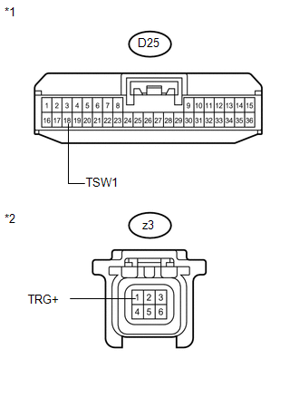
D25-18 (TSW1) - z3-1 (TRG+) |
Always |
Below 1 Ω |
|
D25-18 (TSW1) - Body ground |
Always |
10 kΩ or higher |
|
z3-1 (TRG+) - Body ground |
Always |
10 kΩ or higher |
|
*1 |
Front view of wire harness connector (to Certification ECU (Smart Key ECU Assembly)) |
|
*2 |
Front view of wire harness connector (to Front Door Outside Handle Assembly (for Driver Side)) |
| NG | |
REPAIR OR REPLACE HARNESS OR CONNECTOR |
|
|
5. |
INSPECT CERTIFICATION ECU (SMART KEY ECU ASSEMBLY) (LOCK SENSOR SIGNAL INPUT) |
(a) Reconnect the certification ECU (smart key ECU assembly) connector.
(b) Reconnect the front door outside handle assembly (for driver side) connector.
(c) Measure the voltage and check for pulses according to the value(s) in the table below.
Standard:
|
Tester Connection |
Condition |
Specified Condition |
|---|---|---|
|
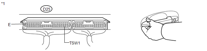
D25-18 (TSW1) - D25-15 (E) |
|
Pulse generation |
|
D25-18 (TSW1) - D25-15 (E) |
|
Below 2 V |
|
*1 |
Component with harness connected (Certification ECU (Smart Key ECU Assembly)) |
| OK | |
REPLACE CERTIFICATION ECU (SMART KEY ECU ASSEMBLY) |
| NG | |
REPLACE FRONT DOOR OUTSIDE HANDLE ASSEMBLY (for Driver Side) |
 Front Passenger Side Door Entry Lock and Unlock Functions do not Operate
DESCRIPTION
When the entry lock and unlock functions do not operate only for the front passenger
door, an error in output request codes from the front passenger door or malfunction
in the front d ...
 Front Passenger Side Door Entry Lock Function does not Operate
DESCRIPTION
If the front passenger door entry unlock function operates normally, but its
entry lock function does not, this means that the request code from the front passenger
door is being outp ...
Other materials about Toyota Venza:
System Description
SYSTEM DESCRIPTION
1. OUTLINE OF THE COMBINATION METER ASSEMBLY
(a) Meter or Gauge
Item
Detail
Speedometer
Indicates the vehicle speed based on a signal received from the skid
control ECU. (CAN (CAN No ...
Intake Manifold Runner Control Stuck Open (Bank 1) (P2004,P2006)
DESCRIPTION
The tumble control valve is built into the intake manifold. The tumble control
valve is composed of a position sensor and a DC motor. The DC motor opens and closes
the tumble control valve in response to signals from the ECM. The position sens ...
Installation
INSTALLATION
PROCEDURE
1. INSTALL DRIVE MONITOR SWITCH
(a) Engage the 4 claws to install the driver monitor switch.
2. INSTALL RADIO AND DISPLAY RECEIVER ASSEMBLY WITH BRACKET (for Radio and Display ...

0.1166