Toyota Venza: Cruise Control Main Switch
Components
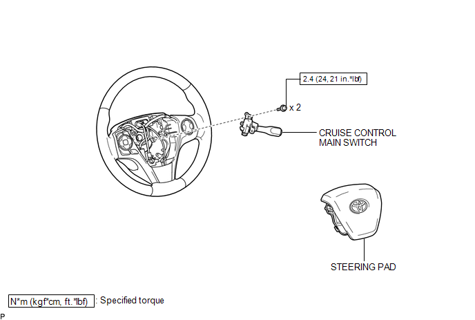
COMPONENTS
ILLUSTRATION
Removal
REMOVAL
PROCEDURE
1. REMOVE STEERING PAD
(See page .gif) )
)
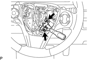
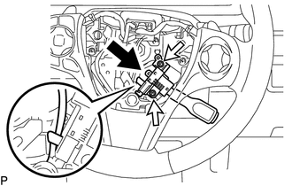
2. REMOVE CRUISE CONTROL MAIN SWITCH
|
(a) Remove the 2 screws. |
|
|
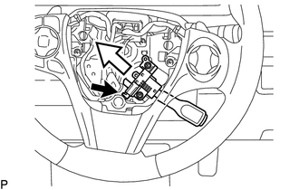
(b) Disconnect the connector and remove the cruise control main switch shown in the illustration. |
|
Inspection
INSPECTION
PROCEDURE
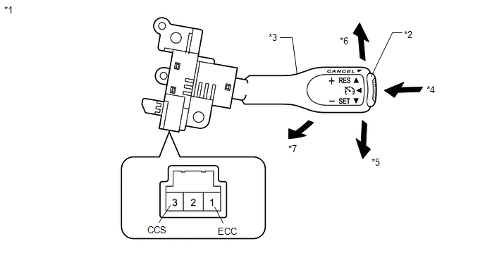
1. INSPECT CRUISE CONTROL MAIN SWITCH
(a) for vehicles without vehicle-to-vehicle distance control mode:
(1) Measure the resistance according to the value(s) in the table below.
 Text in Illustration
|
*1 |
Component without harness connected: (Cruise Control Main Switch) |
*2 |
Main Switch |
|
*3 |
Lever |
*4 |
ON/OFF |
|
*5 |
- SET |
*6 |
+ RES |
|
*7 |
CANCEL |
- |
- |
Standard Resistance:
|
Tester Connection |
Switch Condition |
Specified Condition |
|---|---|---|
|
1 (ECC) - 3 (CCS) |
Main Switch off*1 |
1 MΩ or higher |
|
Main Switch on |
Below 2.5 Ω |
|
|
+ RES |
235 to 245 Ω |
|
|
- SET |
617 to 643 Ω |
|
|
CANCEL |
1509 to 1571 Ω |
*1: Lever is in neutral position
If the result is not as specified, replace the cruise control main switch.
Installation
INSTALLATION
PROCEDURE
1. INSTALL CRUISE CONTROL MAIN SWITCH
(a) Connect the connector.
|
(b) Install the cruise control main switch with the 2 screws shown in the illustration. Torque: 2.4 N·m {24 kgf·cm, 21 in·lbf} |
|
2. INSTALL STEERING PAD
(See page .gif) )
)
 Cruise Control
...

Other materials about Toyota Venza:
Removal
REMOVAL
PROCEDURE
1. REMOVE INSTRUMENT PANEL SAFETY PAD ASSEMBLY
(See page )
2. REMOVE NO. 1 ANTENNA CORD SUB-ASSEMBLY
(a) Disengage the 7 clamps and remove the No. 1 antenna cord sub-assembly.
3. REMOVE ROOF HEADLINING ASSEMBLY
(See page )
4. REMO ...
Starter Relay Circuit High (P0617)
DESCRIPTION
While the engine is being cranked, battery voltage is applied to terminal STA
of the TCM.
If the TCM detects the Starter Control (STA) signal while the vehicle is being
driven, it determines that there is a malfunction in the STA circuit. The ...
Diagnostic Trouble Code Chart
DIAGNOSTIC TROUBLE CODE CHART
ACTIVE TORQUE CONTROL 4WD SYSTEM
DTC Code
Detection Item
Trouble Area
See page
C1241/94
Low Power Supply Voltage
1. Battery
2. ECU-IG1 fuse
...

0.1245