Toyota Venza: Installation
INSTALLATION
PROCEDURE
1. REPAIR INSTRUCTION
(a) Clean the vehicle body surface.
(1) Using a heat light, heat the vehicle body surface.
Heating Temperature|
Item |
Temperature |
|---|---|
|
Vehicle Body |
40 to 60°C (104 to 140°F) |
NOTICE:
Do not heat the vehicle body excessively.
(2) Wipe off any tape adhesive residue with cleaner.
(b) Installation temperature
(1) When the ambient temperature is below 15°C (59°F), perform the installation procedure after warming the vehicle body surface (installation surface of the door frame) and tape up to between 20 and 30°C (68 and 86°F) using a heat light. When the ambient temperature is above 35°C (95°F), cool the vehicle body surface (installation surface of the door frame) and tape down to between 20 and 30°C (68 and 86°F) prior to installation.
HINT:
- The most appropriate temperature for installing the tape is 25°C (77°F).
- When the temperature is low, the tape turns stiff and comes off easily. When the temperature is high, the tape looses elasticity.
(c) Before installation
(1) Remove any coating roughness or dirt on and around the vehicle body surface where the tape will be installed (installation surface of the door frame). If any roughness or dirt remains when pressing the tape onto the surface, air will be trapped under the tape and result in a poor appearance.
HINT:
Spray water on the shop floor to settle any dust.
(d) Key points for handling the tape
(1) The tape bends and rolls up easily. Store the tape between flat pieces of cardboard or other similar objects and keep it dry and level.
NOTICE:
Do not bend the tape or leave it in high temperature places.
(e) Key points for installation of the tape (how to use a squeegee and installation procedure for flat surfaces)
NOTICE:
- Position the tape accurately to achieve a neat finish and to avoid peeling.
- The tape cannot be reused because it deforms and will not fit any more after being removed.
(1) To avoid air bubbles, slightly raise the part of the tape that is going to be applied so that its adhesive surface does not touch the vehicle body while applying the tape. Tilt the squeegee at 40 to 50° (pressing forward) or 30 to 45° (pulling) to the vehicle body surface and press the tape onto the vehicle body surface with a force of 20 to 30 N (2 to 3 kgf) at a constant slow speed of 3 to 7 cm (1.18 to 2.76 in.) per second.
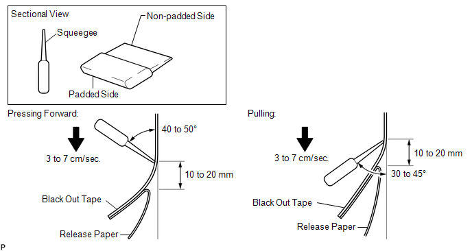
NOTICE:
Be sure to observe the specified pressing speed, force, and angle of the squeegee to avoid wrinkles or air bubbles.
HINT:
- Either angle of the squeegee (pressing forward or pulling) is acceptable.
- Be sure to apply the tape while removing the release paper 10 to 20 mm (0.394 to 0.787 in.) from the edge of the squeegee.
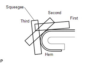
(f) Key points for installation of the tape (how to use a squeegee and installation procedure for hemmed surfaces)
|
(1) If it is difficult to apply the tape, install it in several steps as shown in the illustration. Use your fingers or the padded surface of a squeegee to slowly apply the tape to the hem of the vehicle, especially for a small hem. HINT: When applying tape to the backside of a hem, remove the release paper and use your fingers or the padded surface of a squeegee. |
|
(g) Key points for installation of the tape (how to use a squeegee and installation procedure for corners)
(1) Remove the release paper and apply the tape carefully with your fingers.
(2) Before applying the tape to each corner, heat the tape using a heat light and gradually apply it, avoiding wrinkles on the tape to achieve a neat finish.
(h) Check after installation
(1) After completing the application, check if the tape is applied neatly. If the tape is not applied neatly, reapply using new tape.
NOTICE:
Do not reuse the tape.
2. INSTALL NO. 1 BLACK OUT TAPE
(a) Refer to the illustration to position the No. 1 black out tape.
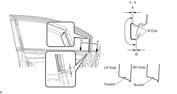 Standard Measurement
|
Dimension |
Measurement |
|---|---|
|
A |
+1.5 mm (+0.0591 in.) |
|
B |
-1.0 mm (-0.0394 in.) |
|
C |
7.0 mm (0.276 in.) |
(b) Remove the release paper and apply the tape.
3. INSTALL FRONT DOOR LOWER OUTSIDE STRIPE
(a) Refer to the illustration to position the front door lower outside stripe.
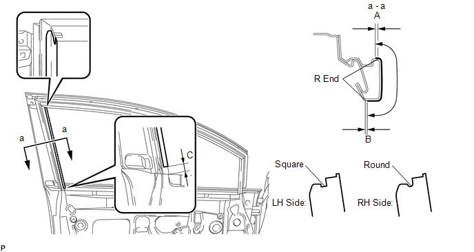 Standard Measurement
|
Dimension |
Measurement |
|---|---|
|
A |
+1.5 mm (+0.0591 in.) |
|
B |
-1.0 mm (-0.0394 in.) |
|
C |
7.5 mm (0.295 in.) |
(b) Remove the release paper and apply the stripe.
4. INSTALL FRONT DOOR STRIPE
(a) Refer to the illustration to position the front door stripe.
 Standard Measurement
|
Dimension |
Measurement |
|---|---|
|
A |
+1.5 mm (+0.0591 in.) |
|
B |
-1.0 mm (-0.0394 in.) |
(b) Remove the release paper and apply the stripe.
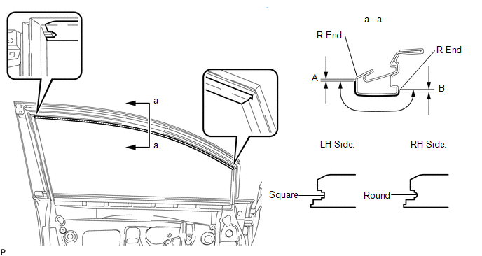
5. CONNECT FRONT DOOR WEATHERSTRIP
.gif)
6. INSTALL FRONT DOOR GLASS RUN
7. INSTALL FRONT DOOR GLASS SUB-ASSEMBLY
8. INSTALL FRONT DOOR SERVICE HOLE COVER
9. INSTALL FRONT NO. 1 SPEAKER ASSEMBLY
10. INSTALL DOOR SIDE AIRBAG SENSOR
11. INSTALL DOOR FRAME GARNISH
12. INSTALL FRONT DOOR INSIDE HANDLE SUB-ASSEMBLY
13. INSTALL FRONT DOOR TRIM BOARD SUB-ASSEMBLY
14. INSTALL COURTESY LIGHT ASSEMBLY
15. INSTALL POWER WINDOW REGULATOR MASTER SWITCH ASSEMBLY WITH FRONT DOOR ARMREST BASE PANEL (for Driver Side)
16. INSTALL POWER WINDOW REGULATOR SWITCH ASSEMBLY WITH FRONT DOOR ARMREST BASE PANEL (for Front Passenger Side)
17. INSTALL FRONT DOOR INSIDE HANDLE BEZEL PLUG
18. CONNECT CABLE TO NEGATIVE BATTERY TERMINAL
NOTICE:
When disconnecting the cable, some systems need to be initialized after the cable
is reconnected (See page ).
19. INSPECT SRS WARNING LIGHT
(See page )
20. INITIALIZE POWER WINDOW CONTROL SYSTEM
(See page )
 Components
COMPONENTS
ILLUSTRATION
ILLUSTRATION
ILLUSTRATION
...
 Removal
REMOVAL
PROCEDURE
1. DISCONNECT CABLE FROM NEGATIVE BATTERY TERMINAL
CAUTION:
Wait at least 90 seconds after disconnecting the cable from the negative (-)
battery terminal to disable the SRS sys ...
Other materials about Toyota Venza:
Brake Switch "A" Circuit (P0571)
DESCRIPTION
When the brake pedal is depressed, the stop light switch assembly sends a signal
to the ECM. When the ECM receives this signal, it cancels the cruise control. The
fail-safe function operates to enable normal driving even if there is a malfunct ...
TRAC OFF Indicator Light Remains ON
DESCRIPTION
The skid control ECU is connected to the combination meter via CAN communication.
Pressing the VSC OFF switch turns off traction control and pressing and holding
this switch turns off traction and VSC controls. If TRAC control is turned off,
...
Removal
REMOVAL
PROCEDURE
1. REMOVE RADIATOR ASSEMBLY AND FAN ASSEMBLY WITH MOTOR
HINT:
See page
2. REMOVE FAN
(a) Remove the nut and fan.
3. REMOVE NO. 2 FAN
(a) Remove the nut and No. 2 f ...

0.2268