
Toyota Venza: Components
COMPONENTS
ILLUSTRATION
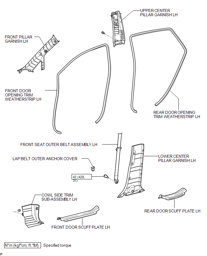
ILLUSTRATION
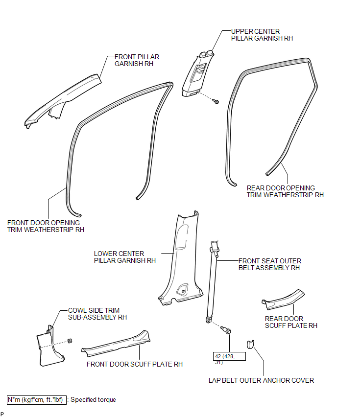
ILLUSTRATION
.png)
ILLUSTRATION
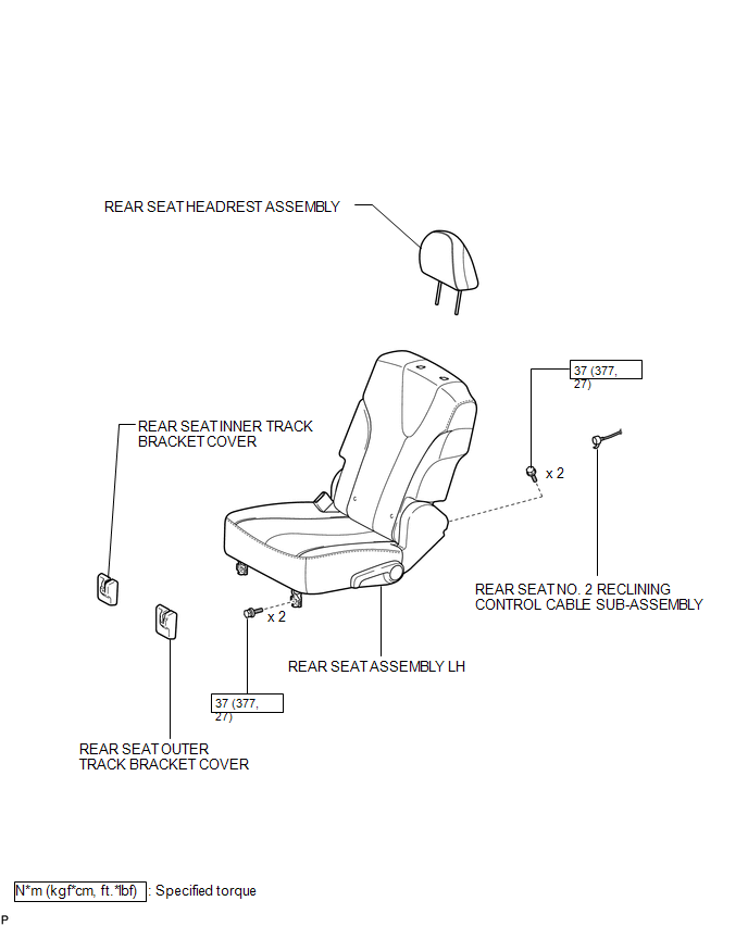
ILLUSTRATION
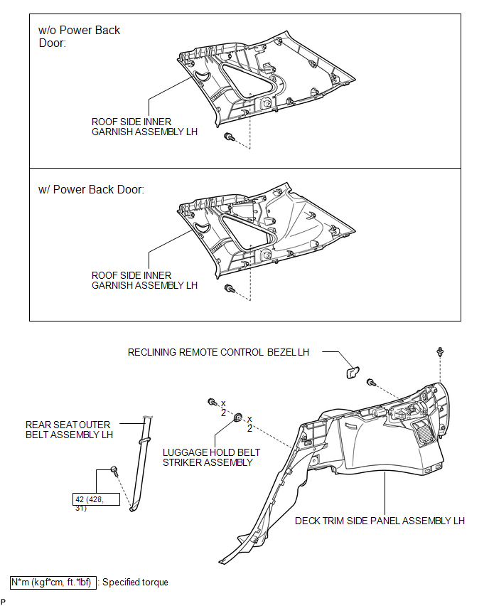
ILLUSTRATION
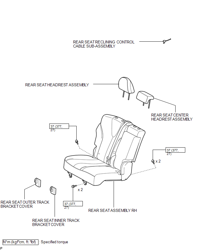
ILLUSTRATION
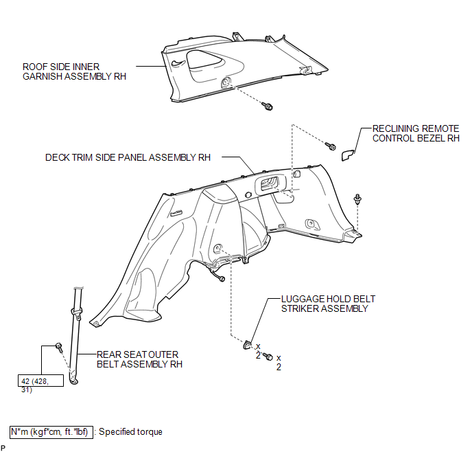
ILLUSTRATION
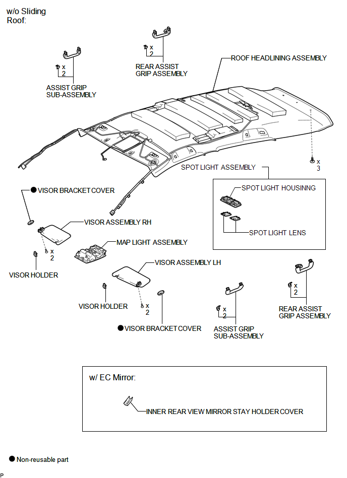
ILLUSTRATION
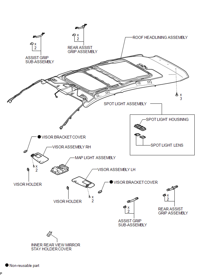
ILLUSTRATION
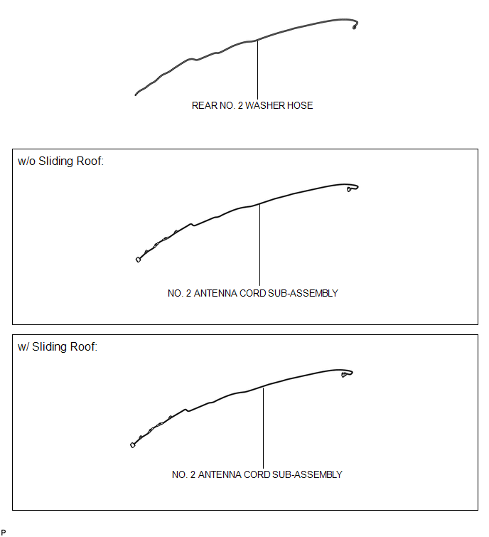
ILLUSTRATION
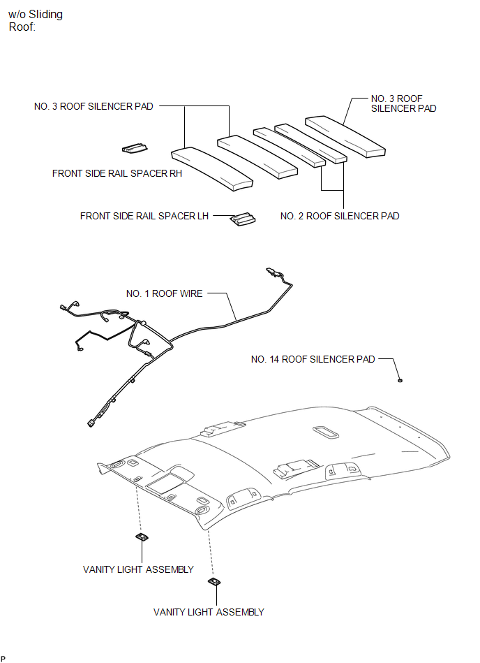
ILLUSTRATION
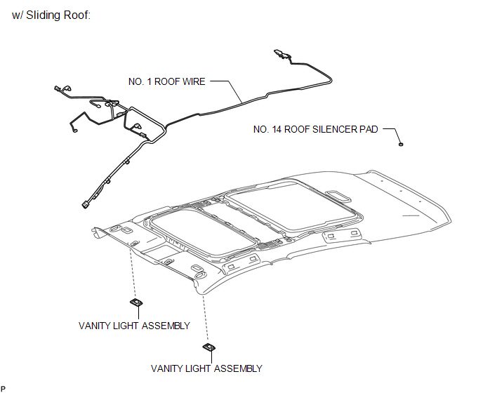
 Roof Headlining
...
 Disassembly
DISASSEMBLY
PROCEDURE
1. REMOVE NO. 2 ANTENNA CORD SUB-ASSEMBLY (w/o Sliding Roof)
2. REMOVE NO. 2 ANTENNA CORD SUB-ASSEMBLY (w/ Sliding Roof)
3. REMOVE VANITY LIGHT ASSEMBLY
(a) Remove the ...
Other materials about Toyota Venza:
Removal
REMOVAL
PROCEDURE
1. DISCONNECT CABLE FROM NEGATIVE BATTERY TERMINAL
NOTICE:
When disconnecting the cable, some systems need to be initialized after the cable
is reconnected (See page ).
2. REMOVE RADIATOR ASSEMBLY
HINT:
See page
3. REMOVE V-RIBBE ...
Removal
REMOVAL
PROCEDURE
1. DRAIN AUTOMATIC TRANSAXLE FLUID
2. REMOVE FRONT FRAME ASSEMBLY
See page
3. SUPPORT ENGINE ASSEMBLY
4. REMOVE BELT
5. REMOVE AUTOMATIC TRANSAXLE OIL PAN SUB-ASSEMBLY
(a) Remove the 18 bolts and automatic transa ...
Installation
INSTALLATION
PROCEDURE
1. INSTALL ROOF DRIP SIDE FINISH MOULDING CLIP (w/o Sliding Roof)
NOTICE:
If reusing the clips, do not remove the double-sided tape remaining
on the clips and where the clips will be installed on the body.
If installi ...

0.1262