Toyota Venza: Components
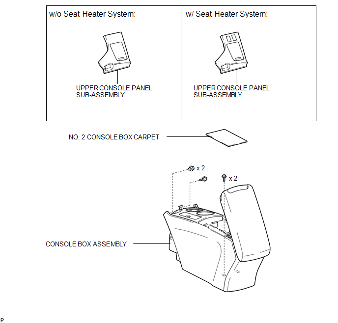
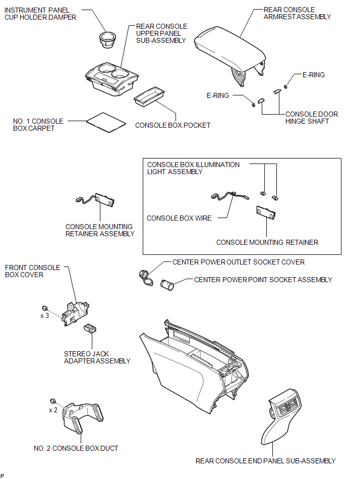
COMPONENTS
ILLUSTRATION
ILLUSTRATION

 Disassembly
DISASSEMBLY
PROCEDURE
1. REMOVE NO. 1 CONSOLE BOX CARPET
(a) Remove the No. 1 console box carpet.
2. REMOVE INSTRUMENT PANEL CUP HOLDER DA ...
Other materials about Toyota Venza:
Removal
REMOVAL
PROCEDURE
1. DISCHARGE FUEL SYSTEM PRESSURE
HINT:
(See page ).
2. DISCONNECT CABLE FROM NEGATIVE BATTERY TERMINAL
NOTICE:
When disconnecting the cable, some systems need to be initialized after the cable
is reconnected (See page ).
3. REMOV ...
Installation
INSTALLATION
PROCEDURE
1. INSTALL REAR SEAT OUTER BELT ASSEMBLY
(a) Engage the 2 guides.
(b) Install the rear seat outer belt assembly with the 2 bolts.
Torque:
Bolt <A> :
7.5 N·m {77 kg ...
Tongue Plate Stopper
Components
COMPONENTS
ILLUSTRATION
Replacement
REPLACEMENT
PROCEDURE
1. REMOVE TONGUE PLATE STOPPER
(a) Slide the tongue plate above the installation position of the tongue
plate stopper, and temporarily hold it with adhesive tape.
...

0.1241