Toyota Venza: Disassembly
DISASSEMBLY
PROCEDURE
1. PRECAUTION
NOTICE:
After turning the ignition switch off, waiting time may be required before disconnecting
the cable from the negative (-) battery terminal. Therefore, make sure to read the
disconnecting the cable from the negative (-) battery terminal notices before proceeding
with work (See page .gif) ).
).
2. DISCONNECT CABLE FROM NEGATIVE BATTERY TERMINAL
CAUTION:
Wait at least 90 seconds after disconnecting the cable from the negative (-)
battery terminal to disable the SRS system (See page
).
NOTICE:
When disconnecting the cable, some systems need to be initialized after the cable
is reconnected (See page ).
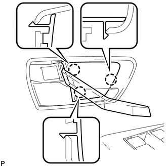
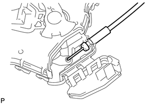
3. REMOVE FRONT DOOR INSIDE HANDLE BEZEL PLUG
|
(a) Using a moulding remover, disengage the 3 claws and remove the front door inside handle bezel plug. |
|
4. REMOVE POWER WINDOW REGULATOR MASTER SWITCH ASSEMBLY WITH FRONT DOOR ARMREST BASE PANEL (for Driver Side)
|
(a) Using a moulding remover, disengage the 2 clips and 4 claws. |
|
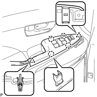
(b) Disconnect the connector and remove the power window regulator master switch assembly with front door armrest base panel.
5. REMOVE POWER WINDOW REGULATOR SWITCH ASSEMBLY WITH FRONT DOOR ARMREST BASE PANEL (for Front Passenger Side)
6. REMOVE COURTESY LIGHT ASSEMBLY
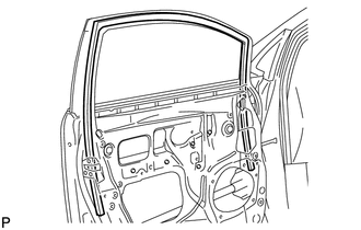
7. REMOVE FRONT DOOR TRIM BOARD SUB-ASSEMBLY
|
(a) Remove the 2 screws. |
|
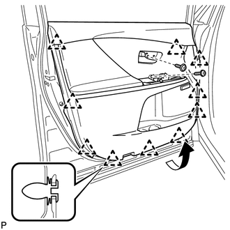
(b) Using a clip remover, disengage the 10 clips.
(c) Pull out the front door trim board sub-assembly in the direction indicated by the arrow as shown in the illustration.
(d) Raise the front door trim board sub-assembly and remove the front door trim board sub-assembly together with the front door inner glass weatherstrip.
|
(e) Disengage the 2 claws and disconnect the front door inside handle sub-assembly. |
|
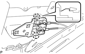
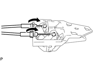
8. REMOVE FRONT DOOR INSIDE HANDLE SUB-ASSEMBLY
|
(a) Disconnect the front door lock remote control cable and front door inside locking cable, and remove the front door inside handle sub-assembly. |
|
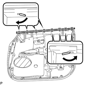
9. REMOVE FRONT DOOR INNER GLASS WEATHERSTRIP
|
(a) Disengage the 8 claws and remove the front door inner glass weatherstrip from the front door trim board sub-assembly as shown in the illustration. |
|
10. REMOVE SEAT MEMORY SWITCH (w/ Memory)
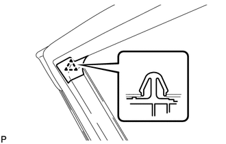
11. REMOVE DOOR FRAME GARNISH
|
(a) Disengage the clip and remove the door frame garnish. HINT: This garnish needs to be replaced with a new one because the clip will break when removing the door frame garnish. |
|
12. REMOVE DOOR SIDE AIRBAG SENSOR
13. REMOVE FRONT NO. 1 SPEAKER ASSEMBLY
14. REMOVE OUTER MIRROR CONTROL ECU ASSEMBLY (w/ Memory)
15. REMOVE FRONT DOOR SERVICE HOLE COVER
|
(a) Disengage the clamp. |
|
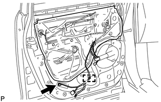
(b) Remove the bolt.
(c) Remove the front door service hole cover.
HINT:
Remove any remaining butyl tape from the door.
16. REMOVE OUTER REAR VIEW MIRROR ASSEMBLY
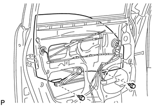
17. REMOVE FRONT DOOR GLASS SUB-ASSEMBLY
(a) Connect the cable to the negative (-) battery terminal.
(b) Connect the power window regulator master switch assembly and move the front door glass sub-assembly so that the door glass bolts can be seen.
(c) Disconnect the cable from the negative (-) battery terminal and power window regulator master switch assembly.
|
(d) Remove the 2 bolts. NOTICE: After the bolts are removed, do not allow the door glass to fall. |
|
|
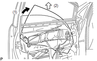
(e) Remove the front door glass sub-assembly as indicated by the arrows, in the order shown in the illustration. NOTICE: Do not damage the door glass. |
|
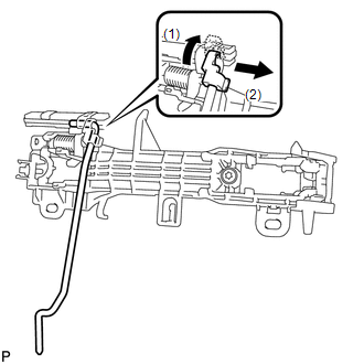
18. REMOVE FRONT DOOR WINDOW REGULATOR ASSEMBLY
|
(a) Disconnect the connector. |
|

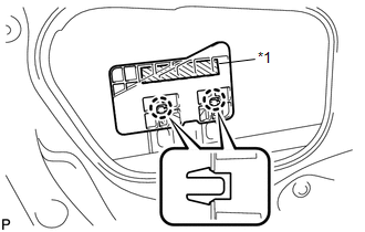
(b) Loosen the temporary bolt.
Text in Illustration|
*1 |
Temporary Bolt |
NOTICE:
Do not remove the temporary bolt. If the temporary bolt is removed, the front door window regulator may fall and cause damage.
(c) Remove the 5 bolts.
(d) Remove the front door window regulator assembly.
(e) Remove the temporary bolt from the front door window regulator assembly.
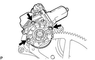
19. REMOVE FRONT POWER WINDOW REGULATOR MOTOR ASSEMBLY
|
(a) Using a T25 "TORX" socket wrench, remove the 3 screws and the front power window regulator motor assembly. |
|
20. REMOVE FRONT DOOR NO. 2 STIFFENER CUSHION
|
(a) Disengage the 2 claws and remove the front door No. 2 stiffener cushion. Text in Illustration
|
|
21. REMOVE FRONT DOOR GLASS RUN
|
(a) Remove the front door glass run. |
|
22. REMOVE FRONT DOOR REAR LOWER FRAME SUB-ASSEMBLY
|
(a) Remove the bolt and front door rear lower frame sub-assembly as shown in the illustration. |
|
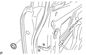
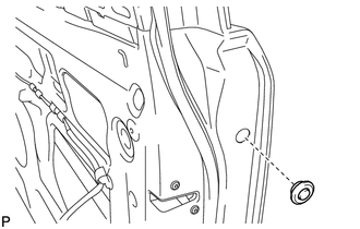
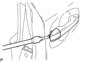
23. REMOVE FRONT DOOR OUTSIDE HANDLE COVER WITH LOCK CYLINDER ASSEMBLY (for Driver Side)
|
(a) Remove the hole plug. |
|
|
(b) Using a T30 "TORX" socket wrench, loosen the screw and remove the front door outside handle cover with lock cylinder assembly. HINT: The screw cannot be removed because it is integrated into the front door outside handle frame sub-assembly. |
|
24. REMOVE FRONT DOOR OUTSIDE HANDLE COVER (for Driver Side)
|
(a) Using a screwdriver, disengage the claw and remove the front door outside handle cover. |
|
25. REMOVE FRONT DOOR OUTSIDE HANDLE COVER (for Front Passenger Side)
|
(a) Remove the hole plug. |
|
|
(b) Using a T30 "TORX" socket wrench, loosen the screw and remove the front door outside handle cover. HINT: The screw cannot be removed because it is integrated into the front door outside handle frame sub-assembly. |
|
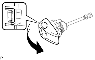
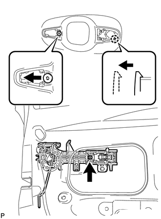
26. REMOVE FRONT DOOR OUTSIDE HANDLE ASSEMBLY (w/o Smart Key System)
|
(a) Move the lever in the direction indicated by the arrow in the illustration. |
|
|
(b) Remove the front door outside handle assembly as shown in the illustration. |
|
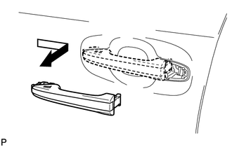
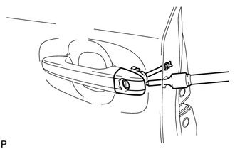
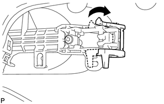
27. REMOVE FRONT DOOR OUTSIDE HANDLE ASSEMBLY (w/ Smart Key System)
|
(a) Disengage the 2 claws. |
|
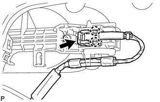
(b) Disconnect the connector.
|
(c) Move the lever in the direction indicated by the arrow in the illustration. |
|
|
(d) Remove the front door outside handle assembly as shown in the illustration. |
|
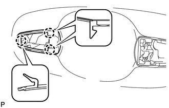
28. REMOVE FRONT DOOR FRONT OUTSIDE HANDLE PAD
|
(a) Disengage the 3 claws and remove the front door front outside handle pad. |
|
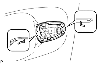
29. REMOVE FRONT DOOR REAR OUTSIDE HANDLE PAD
|
(a) Disengage the 2 claws and remove the front door rear outside handle pad. |
|
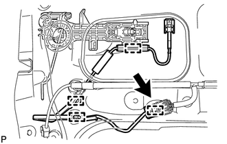
30. REMOVE FRONT DOOR LOCK ASSEMBLY
|
(a) Disconnect the connector. |
|
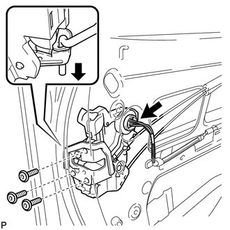
(b) Using a T30 "TORX" socket wrench, remove the 3 screws.
(c) Slide the front door lock assembly downward, and remove the front door lock assembly and cables as a unit.
|
(d) Remove the door lock wiring harness seal from the front door lock assembly. |
|
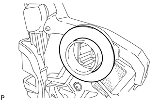
31. REMOVE FRONT DOOR LOCK REMOTE CONTROL CABLE ASSEMBLY
|
(a) Remove the front door lock remote control cable assembly. |
|
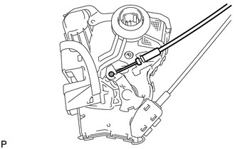
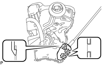
32. REMOVE FRONT DOOR INSIDE LOCKING CABLE ASSEMBLY
|
(a) Using a screwdriver, disengage the 3 claws. HINT: Tape the screwdriver tip before use. |
|
|
(b) Remove the front door inside locking cable assembly. |
|
33. REMOVE ELECTRICAL KEY WIRE HARNESS (w/ Smart Key System)
|
(a) Disconnect the connector. |
|
(b) Disengage the 4 clamps and remove the electrical key wire harness.
34. REMOVE FRONT DOOR OUTSIDE HANDLE FRAME SUB-ASSEMBLY
|
(a) Using a T30 "TORX" socket wrench, loosen the screw. |
|
(b) Slide the front door outside handle frame sub-assembly to disengage the door handle nut and claw of the front door outside handle frame sub-assembly, and then remove it.
35. REMOVE FRONT DOOR LOCK OPEN ROD
|
(a) Remove the front door lock open rod as indicated by the arrows, in the order shown in the illustration. |
|
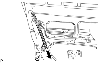
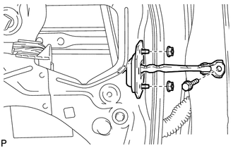
36. REMOVE FRONT DOOR CHECK ASSEMBLY
|
(a) Remove the bolt, 2 nuts and front door check assembly. |
|
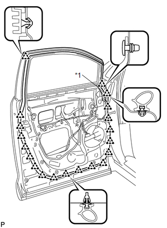
37. REMOVE FRONT DOOR WEATHERSTRIP
|
(a) Using a clip remover, disengage the 20 clips and remove the front door weatherstrip. Text in Illustration
|
|
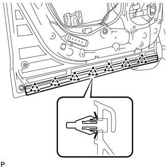
38. REMOVE FRONT DOOR PANEL PROTECTOR
|
(a) Disengage the 7 clips and remove the front door panel protector. |
|
39. REMOVE FRONT DOOR STRIPE
40. REMOVE FRONT DOOR LOWER OUTSIDE STRIPE
41. REMOVE NO. 1 BLACK OUT TAPE
42. REMOVE FRONT DOOR OUTSIDE MOULDING
43. REMOVE FRONT DOOR BELT MOULDING
44. REMOVE FRONT DOOR REAR WINDOW FRAME MOULDING
45. REMOVE FRONT DOOR SCUFF PLATE
46. REMOVE COWL SIDE TRIM SUB-ASSEMBLY
47. REMOVE FRONT DOOR PANEL SUB-ASSEMBLY
48. REMOVE FRONT DOOR UPPER WINDOW FRAME MOULDING
49. REMOVE FRONT DOOR FRONT WINDOW FRAME MOULDING
 Components
COMPONENTS
ILLUSTRATION
ILLUSTRATION
ILLUSTRATION
ILLUSTRATION
ILLUSTRATION
ILLUSTRATION
ILLUSTRATION
...
 Adjustment
ADJUSTMENT
CAUTION / NOTICE / HINT
CAUTION:
Before adjusting the door positions of vehicles equipped with side and curtain
shield airbags, be sure to disconnect the battery. After adjustment, c ...
Other materials about Toyota Venza:
Inspection
INSPECTION
PROCEDURE
1. INSPECT GENERATOR CLUTCH PULLEY
(a) Hold the generator rotor using SST, and turn the clutch pulley clockwise
to check that the outer ring locks.
SST: 09820-63021
Text in Illustration
*1
...
Removal
REMOVAL
PROCEDURE
1. DISCONNECT CABLE FROM NEGATIVE BATTERY TERMINAL
NOTICE:
When disconnecting the cable, some systems need to be initialized after the cable
is reconnected (See page ).
2. REMOVE RADIATOR ASSEMBLY
HINT:
See page
3. REMOVE V-RIBBE ...
Inspection
INSPECTION
PROCEDURE
1. INSPECT BRAKE VACUUM CHECK VALVE ASSEMBLY
(a) Check that there is ventilation from the booster to the engine, and
no ventilation from the engine to the booster.
If the results are not as specified, replace the brake ...

0.1761