Toyota Venza: Diagnosis System
DIAGNOSIS SYSTEM
1. DESCRIPTION
(a) Diagnostic System
When troubleshooting a vehicle with a diagnostic system, the only difference from the usual troubleshooting procedure is connecting the Techstream to the vehicle and reading various data output from the vehicle steering lock ECU (steering lock actuator assembly).
The steering lock ECU (steering lock actuator assembly) records DTCs when the computer detects a malfunction in the computer itself or in its circuits.
To check the DTCs, connect the Techstream to the DLC3 on the vehicle. The Techstream enables the DTCs to be cleared, the indicators to be activated, and the Data List to be checked.
(b) The diagnosis information of the steering lock ECU (steering lock actuator assembly) is transmitted to the Techstream via the certification ECU (smart key ECU assembly) as the steering lock ECU (steering lock actuator assembly) is not connected to CAN.
(c) Check the DLC3.
(1) Check the DLC3 (See page .gif) ).
).
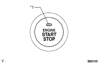
2. WARNING FUNCTION OF ENGINE SWITCH INDICATOR
(a) The steering lock ECU (steering lock actuator assembly) blinks the LED indicator of the engine switch when any of the following problems occurs in the system:
 Text in Illustration
|
*1 |
Indicator Light |
|
Detection Item |
Indicator Light Blink Pattern |
Indication Status |
Countermeasure |
|---|---|---|---|
|
Steering lock is still not released |
|
The motor operates to release the steering lock, but the steering lock cannot be released (e.g. the lock bar is stuck in the steering column). |
Push the engine switch while turning the steering wheel left or right. |
|
Malfunction in push-button start system |
|
|
Troubleshoot by following "How to Proceed with Troubleshooting" (See
page |
 Terminals Of Ecu
TERMINALS OF ECU
1. STEERING LOCK ECU (STEERING LOCK ACTUATOR ASSEMBLY)
Terminal No. (Symbol)
Wiring Color
Terminal Description
Condition
Spe ...
 Dtc Check / Clear
DTC CHECK / CLEAR
1. CHECK DTCS
(a) Turn the engine switch off.
(b) Connect the Techstream to the DLC3.
(c) Turn the engine switch on (IG).
(d) Turn the Techstream on.
(e) Check for DTCs. Enter ...
Other materials about Toyota Venza:
Inspection
INSPECTION
PROCEDURE
1. INSPECT TIE ROD ASSEMBLY LH
(a) Secure the tie rod assembly LH in a vise.
(b) Install the nut to the stud bolt.
(c) Flip the ball joint back and forth 5 times.
(d) Set a to ...
Entire Combination Meter does not Operate
DESCRIPTION
This circuit is the power source circuit for the meter. This circuit provides
two types of power sources; one is a constant power source mainly used as a backup
power source, and the other is an IG power source mainly used for signal transmiss ...
Data List / Active Test
DATA LIST / ACTIVE TEST
1. USING TECHSTREAM
(a) Connect the Techstream to the DLC3.
(b) Monitor the ECU data by following the prompts on the Techstream screen.
HINT:
The Techstream has a "Snapshot" function which records the monitored data. Refe ...

0.1148