Toyota Venza: Components
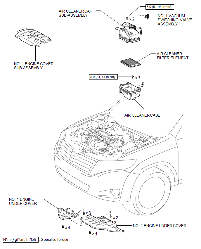
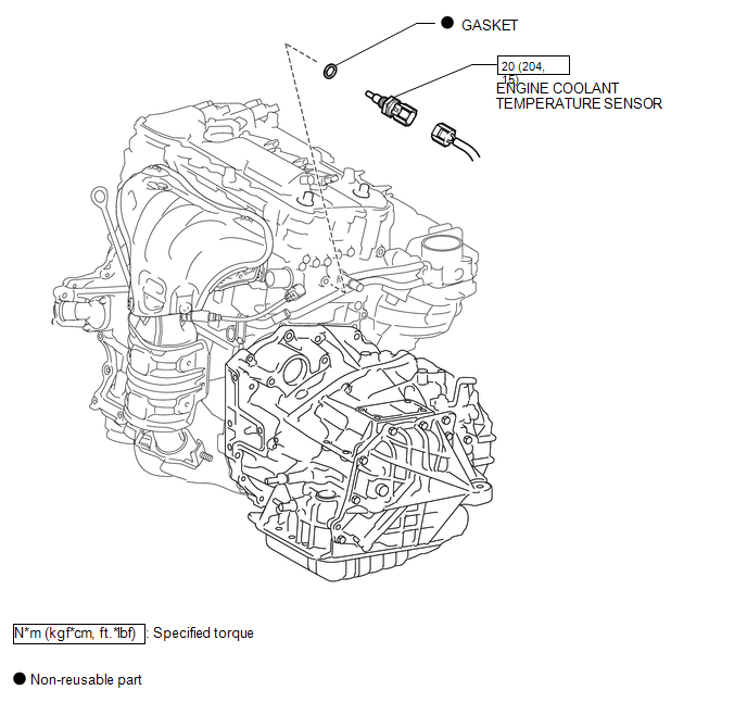
COMPONENTS
ILLUSTRATION
.png)
ILLUSTRATION
ILLUSTRATION

 Inspection
INSPECTION
PROCEDURE
1. INSPECT ENGINE COOLANT TEMPERATURE SENSOR
Text in Illustration
*1
Component without harness connected
(Engine Coolant Temperature Sensor)
...
Other materials about Toyota Venza:
Initialization
INITIALIZATION
1. INITIALIZE SLIDING ROOF ECU (SLIDING ROOF DRIVE GEAR SUB-ASSEMBLY)
NOTICE:
When the sliding roof glass, sliding roof housing or sliding roof ECU
(sliding roof drive gear sub-assembly) is replaced or removed and installed,
t ...
Installation
INSTALLATION
PROCEDURE
1. INSTALL REAR DOOR BELT MOULDING
(a) Engage the 5 claws to install the rear door belt moulding.
2. INSTALL REAR DOOR GLASS SUB-ASSEMBLY
3. INSTALL REAR DOOR WINDOW DIVIS ...
Wheels
If a wheel is bent, cracked or heavily corroded, it should be replaced.
Otherwise, the tire may separate from the wheel or cause loss of handling control.
- Wheel selection
When replacing wheels, care should be taken to ensure that they are equivalent ...

0.1307