Toyota Venza: Components
COMPONENTS
ILLUSTRATION
ILLUSTRATION
ILLUSTRATION
ILLUSTRATION
.png)

 Removal
REMOVAL
PROCEDURE
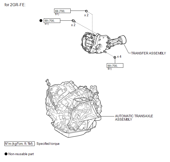
1. REMOVE AUTOMATIC TRANSAXLE ASSEMBLY (for 2GR-FE)
See page
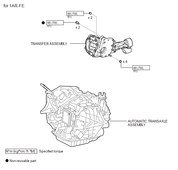
2. REMOVE AUTOMATIC TRANSAXLE ASSEMBLY (for 1AR-FE)
See page
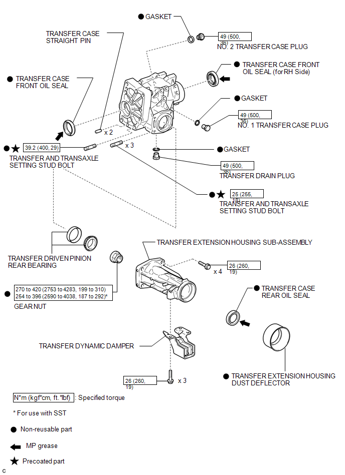
3. REMOVE TRANSFER ASSEMBLY
(a) Remove ...
Other materials about Toyota Venza:
System Description
SYSTEM DESCRIPTION
1. NAVIGATION SYSTEM OUTLINE
(a) Vehicle position tracking methods
It is essential that the navigation system correctly tracks the current vehicle
position and displays it on the map. There are 2 methods to track the current vehicle
p ...
Data List / Active Test
DATA LIST / ACTIVE TEST
1. DATA LIST
Using the Techstream to read the Data List allows the values or states of switches,
sensors, actuators and other items to be read without removing any parts. This non-intrusive
inspection can be very useful because in ...
Precaution
PRECAUTION
1. PRECAUTION FOR DISCONNECTING CABLE FROM NEGATIVE BATTERY TERMINAL
NOTICE:
When disconnecting the cable from the negative (-) battery terminal, initialize
the following system after the terminal is reconnected:
System Name
...

0.1266