Toyota Venza: How To Use This Manual
General Information
GENERAL INFORMATION
1. GENERAL DESCRIPTION
(a) This manual is written in accordance with SAE J2008.
(b) Repair operations can be separated mainly into the following 3 processes:
(1) Diagnosis
(2) Removing / Installing, Replacing, Disassembling / Reassembling, Checking and Adjusting
(3) Final Inspection
(c) The following procedure is omitted from this manual. However, this procedure must be performed.
(1) Use a jack or lift to perform operations.
(2) Clean all removed parts.
(3) Perform a visual check before and after performing any work.
2. INDEX
(a) An alphabetical INDEX section is provided at the end of the manual as a reference to help find the item to be repaired.
3. PREPARATION
(a) Use of Special Service Tools (SST) and Special Service Materials (SSM) may be required, depending on the repair procedure. Be sure to use SST and SSM when they are required and follow the work procedure properly. A list of SST and SSM is in the "Preparation" section of this manual.
4. REPAIR PROCEDURES
(a) A component illustration is placed under the title where necessary.
(b) Non-reusable parts, grease application areas, precoated parts and torque specifications are noted in the component illustrations.
- The following illustration is an example.
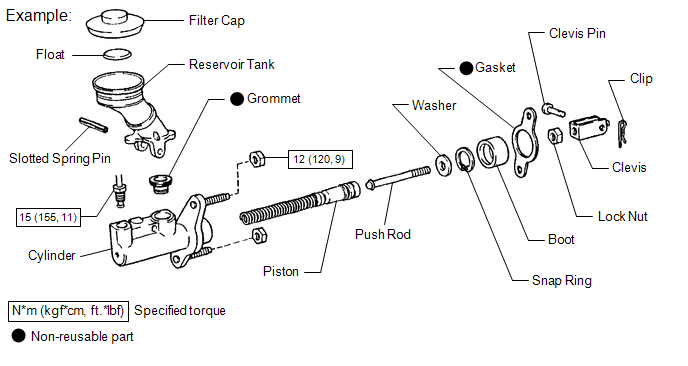
(c) Torque specifications, grease application areas and non-reusable parts are emphasized in the procedures.
HINT:
There are cases where such information can only be explained by using an illustration. In these cases, torque, oil and other information are described in the illustration.
(d) Only items with key points are described in the text. What to do and other details are explained using illustrations next to the text. Both the text and illustrations are accompanied by standard values and notices.
|
Illustration |
What to do and where to do it |
|
Task heading |
What work will be performed |
|
Explanation text |
|
(e) Illustrations of similar vehicle models are sometimes used. In these cases, minor details may be different from the actual vehicle.
(f) Procedures are presented in a step-by-step format.
5. SERVICE SPECIFICATIONS
(a) Specifications are presented in boldface text throughout the manual. The specifications are also found in the "Service Specifications" section for reference.
6. TERM DEFINITIONS
|
CAUTION |
Possibility of injury to you or other people. |
|
NOTICE |
Possibility of damage to components being repaired. |
|
HINT |
Provides additional information to help you perform repairs. |
7. INTERNATIONAL SYSTEM OF UNITS
(a) The units used in this manual comply with the International System of Units (SI UNIT) standard. Other units from the metric system and the English systems are also provided.
- Example:
Torque:
30 N·m {310 kgf·cm, 22 ft·lbf}
 How To Proceed With Troubleshooting
HOW TO PROCEED WITH TROUBLESHOOTING
1. OPERATION FLOW
HINT:
Perform troubleshooting in accordance with the procedure below. The following
is an outline of basic troubleshooting procedure. Confirm ...
 Identification Information
Vehicle Identification And Serial Numbers
VEHICLE IDENTIFICATION AND SERIAL NUMBERS
1. VEHICLE IDENTIFICATION NUMBER
(a) The vehicle identification number is stamped on the vehicle body and on th ...
Other materials about Toyota Venza:
Removal
REMOVAL
CAUTION / NOTICE / HINT
HINT:
Use the same procedure for the RH side and LH side.
The procedure listed below is for the LH side.
PROCEDURE
1. PRECAUTION
CAUTION:
Be sure to read Precaution thoroughly before servicing (See page
...
Rear Speed Sensor RH Circuit (C0210/33,C0215/34,C1273/73,C1274/74,C1332/38,C1333/39)
DESCRIPTION
The speed sensor detects the wheel speed and sends the appropriate signals to
the skid control ECU. These signals are used for the ABS control system.
Speed sensor rotors have rows of alternating N and S magnetic poles (for 2WD)
or 48 serrati ...
Installation
INSTALLATION
CAUTION / NOTICE / HINT
HINT:
Use the same procedure for the RH side and LH side.
The procedure listed below is for the LH side.
PROCEDURE
1. INSTALL REAR AXLE CARRIER SUB-ASSEMBLY
(a) Temporarily install the rea ...

0.132