Toyota Venza: Components
COMPONENTS
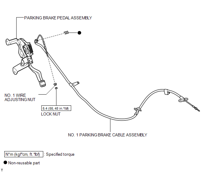
ILLUSTRATION
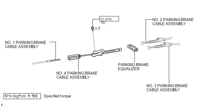
ILLUSTRATION
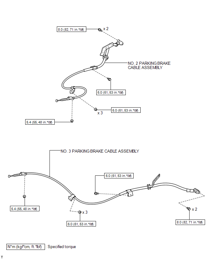
ILLUSTRATION

 Removal
REMOVAL
PROCEDURE
1. REMOVE PARKING BRAKE PEDAL ASSEMBLY
HINT:
Refer to the instructions for Removal of the parking brake pedal assembly (See
page ).
2. REMOVE NO. 1 PARKING BRAKE CABLE ASSEMB ...
Other materials about Toyota Venza:
Luggage compartment light
1. Door position
2. Off
- Adjusting the rear personal/interior lights angle
Push the edge of the light lens.
- To prevent the battery from being discharged
►Vehicles with smart key system
If the personal/interior lights and “ENGIN ...
Engine Stall History (P1603,P1605)
DESCRIPTION
P1603
After starting the engine, this DTC is stored when the engine stops without the
ignition switch being operated.
Using the Techstream, the conditions present when the DTC was stored can be confirmed
by referring to the freeze frame data ...
Disposal
DISPOSAL
PROCEDURE
1. DISPOSE OF FRONT SHOCK ABSORBER ASSEMBLY
(a) Position the front shock absorber assembly level with the piston
rod fully extended. Using a drill, make a hole in the cylinder between A
and B as shown in the illustratio ...

0.1697