Toyota Venza: Components
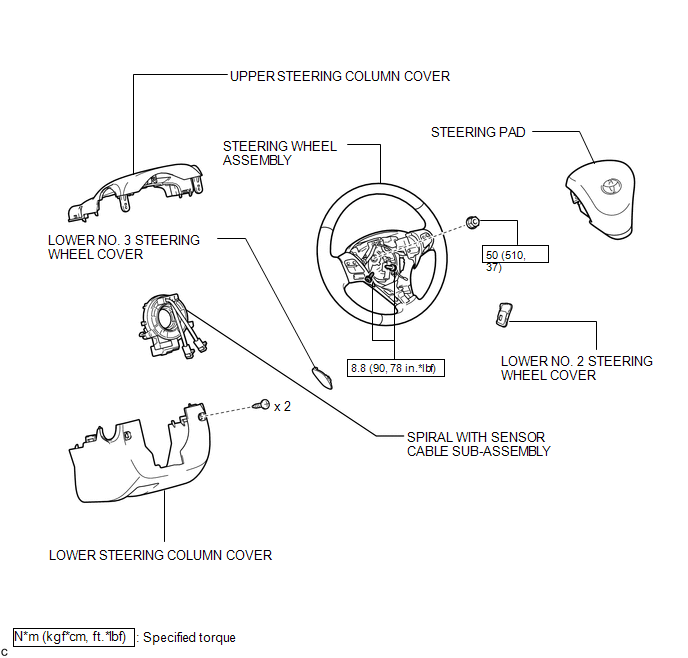
COMPONENTS
ILLUSTRATION

 Installation
INSTALLATION
PROCEDURE
1. INSTALL SPIRAL WITH SENSOR CABLE SUB-ASSEMBLY
(a) Install the spiral with sensor cable sub-assembly (See page
).
NOTICE:
Do not replace the spiral cable with t ...
Other materials about Toyota Venza:
Unlock Position Sensor Signal Circuit
DESCRIPTION
The unlock position sensor is one of the components comprising the steering lock
ECU (steering lock actuator assembly). The sensor switch contact closes when the
steering lock is released. The steering lock release signal is then sent to the
...
Washer Level Warning Switch
Components
COMPONENTS
ILLUSTRATION
Inspection
INSPECTION
PROCEDURE
1. INSPECT LEVEL WARNING SWITCH ASSEMBLY
HINT:
The following check should be performed with the windshield washer motor and
pump installed to the washer jar.
(a) Fill the washe ...
Diagnostic Trouble Code Chart
DIAGNOSTIC TROUBLE CODE CHART
If a trouble code is displayed during the DTC check, check the circuit listed
for the code in the table below (refer to the appropriate page).
HINT:
When the SRS warning light remains on and the DTC output is the norm ...

0.1218