Toyota Venza: Components
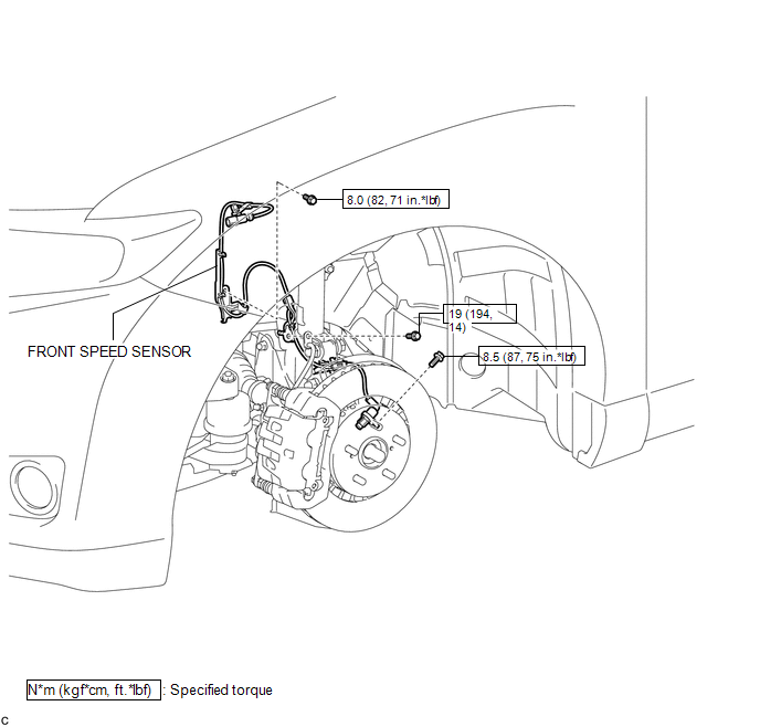
COMPONENTS
ILLUSTRATION
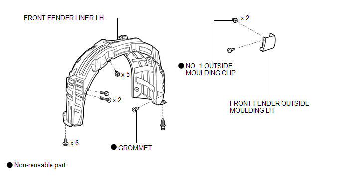
ILLUSTRATION

 Removal
REMOVAL
CAUTION / NOTICE / HINT
HINT:
Use the same procedure for the LH side and RH side.
The following procedure is for the LH side.
If the sensor rotor needs to be replaced, repla ...
Other materials about Toyota Venza:
Components
COMPONENTS
ILLUSTRATION
ILLUSTRATION
ILLUSTRATION
ILLUSTRATION
ILLUSTRATION
...
Disassembly
DISASSEMBLY
PROCEDURE
1. REMOVE STEERING RACK BOOT CLIP (for LH Side)
(a) Using pliers, remove the steering rack boot clip.
2. REMOVE STEERING RACK BOOT CLIP (for RH Side)
HINT:
Perform the same procedure as for the LH side.
3. REMOVE NO. 2 STEERING RAC ...
Air Inlet Damper Control Servo Motor Circuit (B1442/42)
DESCRIPTION
The air inlet control servo motor sends pulse signals to indicate the damper
position to the A/C amplifier. The A/C amplifier activates the motor (normal or
reverse) based on these signals to move the air inlet mode selection air inlet control ...
© 2016-2026 Copyright www.tovenza.com

0.1122
0.1122