Toyota Venza: Components
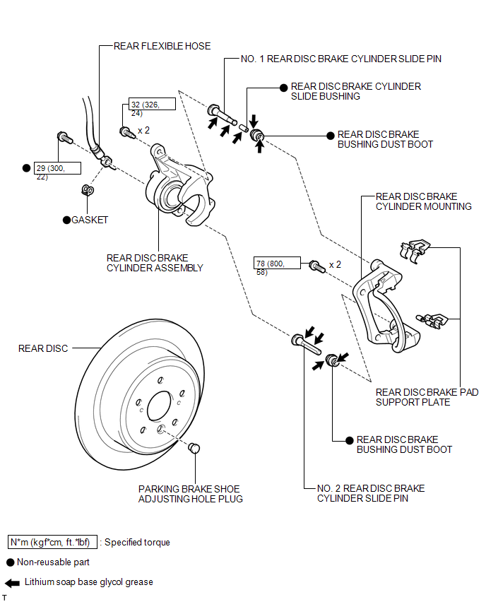
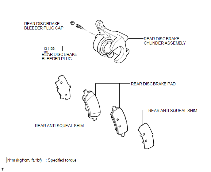
COMPONENTS
ILLUSTRATION
ILLUSTRATION
 Rear Brake
...
 Removal
REMOVAL
CAUTION / NOTICE / HINT
HINT:
Use the same procedure for the LH side and RH side.
The following procedure listed is for the LH side.
PROCEDURE
1. REMOVE REAR WHEEL
2. D ...
Other materials about Toyota Venza:
Precaution
PRECAUTION
NOTICE:
When disconnecting the cable from the negative (-) battery terminal, initialize
the following systems after the cable is reconnected.
System Name
See Procedure
Back Door Closer System
...
Front Crankshaft Oil Seal
Components
COMPONENTS
ILLUSTRATION
Removal
REMOVAL
PROCEDURE
1. REMOVE FRONT WHEEL RH
2. REMOVE NO. 1 ENGINE UNDER COVER
3. SEPARATE FRONT FENDER LINER RH
4. REMOVE FRONT FENDER APRON SEAL RH
5. REMOVE V-RIBBED BELT
6. REMOVE CRANKSHAFT ...
Crankshaft Position Sensor "A" Circuit (P0335,P0339)
DESCRIPTION
The crankshaft position sensor system consists of a crank angle sensor plate
and a pickup coil.
The sensor plate has 34 teeth and is installed on the crankshaft. The pickup
coil is made of wound copper wire, an iron core and magnet. The senso ...

0.1431