
Toyota Venza: Components
COMPONENTS
ILLUSTRATION
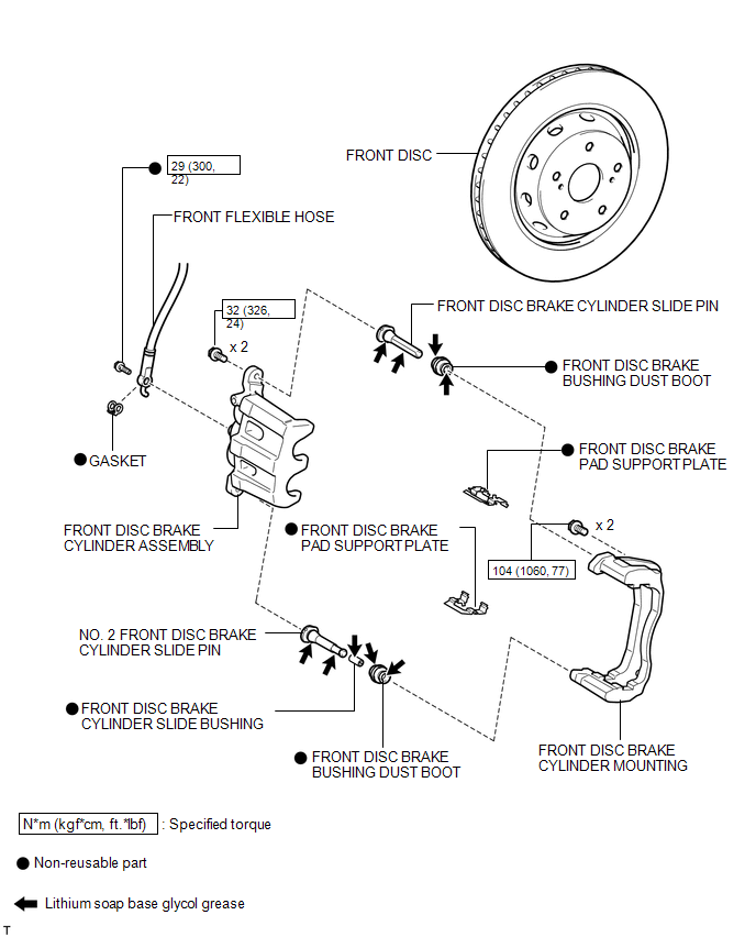
ILLUSTRATION
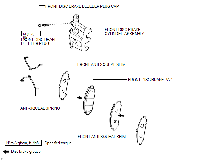
 Front Brake
...
 Removal
REMOVAL
CAUTION / NOTICE / HINT
HINT:
Use the same procedure for the LH side and RH side.
The following procedure listed is for the LH side.
PROCEDURE
1. REMOVE FRONT WHEEL
2. ...
Other materials about Toyota Venza:
Headlight Leveling Ecu
Components
COMPONENTS
ILLUSTRATION
Removal
REMOVAL
PROCEDURE
1. REMOVE HEADLIGHT LEVELING ECU ASSEMBLY
(a) Disconnect the connector.
(b) Remove the bolt and headlight leveling ECU assembly ...
Transponder Key Ecu
Components
COMPONENTS
ILLUSTRATION
Removal
REMOVAL
PROCEDURE
1. REMOVE AIR CONDITIONING UNIT ASSEMBLY
HINT:
Refer to the procedure up to Remove Air Conditioning Unit Assembly (See page
).
2. REMOVE TRANSPONDER KEY ECU ASSEMBLY
(a) ...
Installation
INSTALLATION
PROCEDURE
1. INSTALL REAR SEAT OUTER BELT ASSEMBLY
(a) Engage the 2 guides.
(b) Install the rear seat outer belt assembly with the 2 bolts.
Torque:
Bolt <A> :
7.5 N·m {77 kg ...

0.1559