Toyota Venza: Components
COMPONENTS
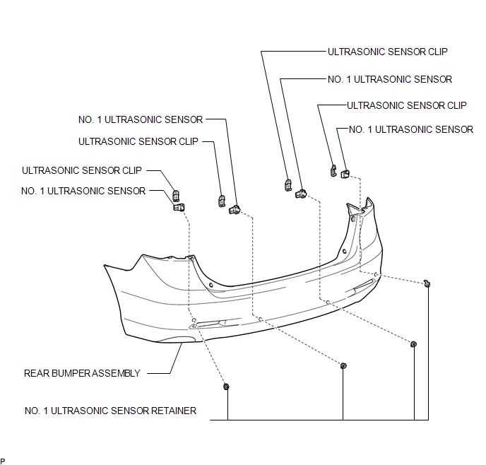
ILLUSTRATION

 Inspection
INSPECTION
PROCEDURE
1. INSPECT NO. 1 ULTRASONIC SENSOR
(a) Measure the resistance according to the value(s) in the table below.
Standard Resistance:
Tester Conne ...
Other materials about Toyota Venza:
Inspection
INSPECTION
PROCEDURE
1. INSPECT ATF TEMPERATURE SENSOR ASSEMBLY
(a) Measure the resistance according to the value(s) in the table below.
Standard Resistance:
Tester Connection
Condition
Sp ...
System Description
SYSTEM DESCRIPTION
1. ILLUMINATED ENTRY SYSTEM
(a) The illuminated entry system has the following control functions:
Control
Outline
Lights that Operate
Actuation Area-linked*2
When a registered k ...
Wireless-linked Return Function does not Operate
DESCRIPTION
When a door is unlocked using the wireless unlock function or entry unlock function,
the certification ECU (smart key ECU assembly) sends a door unlock signal and key
ID signal to the main body ECU (driver side junction block assembly). When t ...

0.1252