Toyota Venza: Components
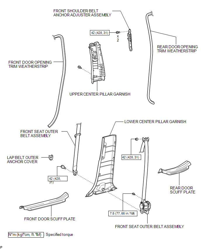
COMPONENTS
ILLUSTRATION

 Precaution
PRECAUTION
CAUTION:
Replace any faulty seat belt components (outer belt, inner belt, bolts, nuts,
adjustable shoulder anchor, tether anchor hardware and other related parts). When
inspecting a v ...
Other materials about Toyota Venza:
Precaution
PRECAUTION
NOTICE:
When disconnecting the cable from the negative (-) battery terminal, initialize
the following systems after the cable is reconnected.
System Name
See Procedure
Power back door system
...
Adjustment
ADJUSTMENT
CAUTION / NOTICE / HINT
CAUTION:
Before adjusting the door positions of vehicles equipped with side and curtain
shield airbags, be sure to disconnect the battery. After adjustment, check that
the SRS warning light is operating normally and ...
Reassembly
REASSEMBLY
PROCEDURE
1. INSTALL NO. 1 SUNSHADE TRIM SUB-ASSEMBLY
(a) Slide and install the No. 1 sunshade trim sub-assembly.
2. INSTALL NO. 2 SUNSHADE TRIM SUB-ASSEMBLY
(a) Slide and ins ...

0.1179