Toyota Venza: Components
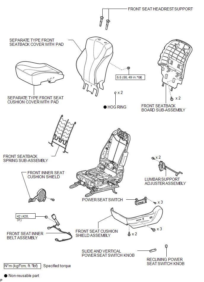
COMPONENTS
ILLUSTRATION
.png)
ILLUSTRATION

 Inspection
INSPECTION
PROCEDURE
1. INSPECT LUMBAR SUPPORT ADJUSTER ASSEMBLY
(a) Check operation of the lumbar support adjuster.
(1) Check if the lumbar support adjuster moves smoothly when the battery is c ...
Other materials about Toyota Venza:
System Description
SYSTEM DESCRIPTION
1. GENERAL
(a) The air conditioning system has the following controls.
Control
Outline
Neural Network Control
This control is capable of performing complex control by artificially
simu ...
Diagnosis System
DIAGNOSIS SYSTEM
1. DESCRIPTION
(a) Diagnostic Trouble Codes (DTCs) can be read from the Data Link Connector
3 (DLC3) of the vehicle. When the rear view monitor system seems to be malfunctioning,
use the Techstream to check for malfunctions and to perfor ...
Installation
INSTALLATION
CAUTION / NOTICE / HINT
HINT:
Use the same procedure for the RH side and LH side.
The procedure listed below is for the LH side.
PROCEDURE
1. INSTALL REAR AXLE CARRIER SUB-ASSEMBLY
(a) Temporarily install the rea ...

0.1574