Toyota Venza: Components
COMPONENTS
ILLUSTRATION
.png)
ILLUSTRATION
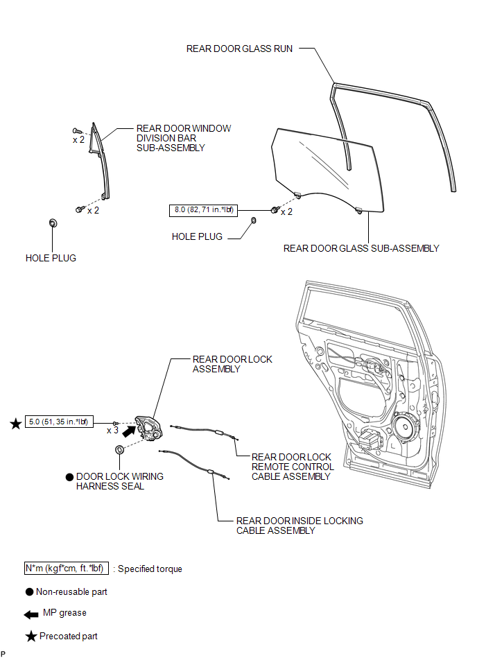
 Rear Door Lock
...
 Removal
REMOVAL
PROCEDURE
1. DISCONNECT CABLE FROM NEGATIVE BATTERY TERMINAL
CAUTION:
Wait at least 90 seconds after disconnecting the cable from the negative (-)
battery terminal to disable the SRS sys ...
Other materials about Toyota Venza:
How To Proceed With Troubleshooting
CAUTION / NOTICE / HINT
HINT:
Use these procedure to troubleshoot the sliding roof system.
*: Use the Techstream.
PROCEDURE
1.
VEHICLE BROUGHT TO WORKSHOP
NEXT
...
Diagnosis System
DIAGNOSIS SYSTEM
1. DESCRIPTION
When troubleshooting OBD II (On-Board Diagnostics) vehicles, an OBD
II scan tool (complying with SAE J1987) must be connected to the DLC3 (Data
Link Connector 3) of the vehicle. Various data in the vehicle ECM ( ...
Diagnosis System
DIAGNOSIS SYSTEM
1. DESCRIPTION
(a) The power back door ECU (power back door motor unit)*1 or back door closer
ECU (multiplex network door ECU)*2 controls the vehicle's back door closer system
functions. Back door closer system data and Diagnostic Tr ...

0.1153