Toyota Venza: Components
COMPONENTS
ILLUSTRATION
ILLUSTRATION
.png)
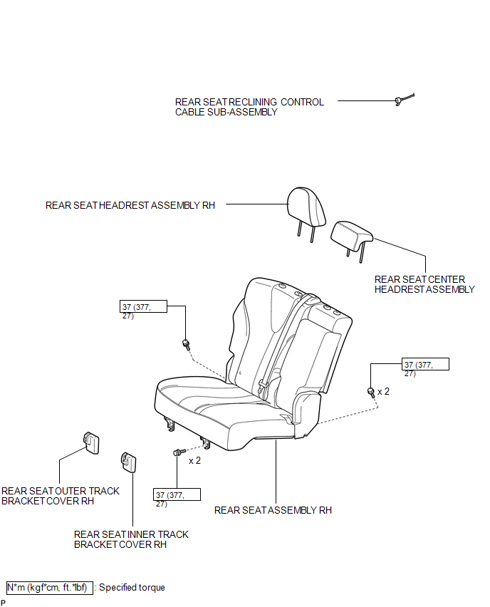
ILLUSTRATION
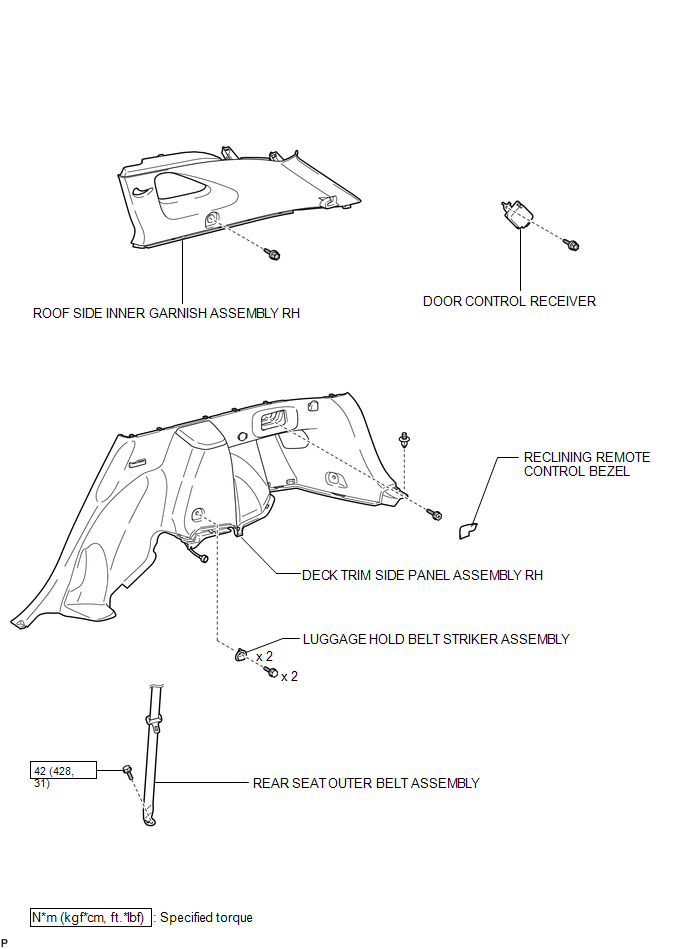
ILLUSTRATION

 Removal
REMOVAL
PROCEDURE
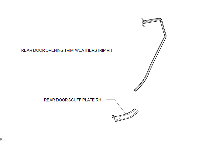
1. REMOVE REAR DOOR SCUFF PLATE RH
HINT:
Use the same procedure for the RH side and LH side (See page
).
2. DISCONNECT REAR DOOR OPENING TRIM WEATHERSTRIP RH
HINT:
Use the s ...
Other materials about Toyota Venza:
Diagnosis System
DIAGNOSIS SYSTEM
1. DESCRIPTION
(a) Lighting system data can be read from the Data Link Connector 3 (DLC3) of
the vehicle. When the system seems to be malfunctioning, use the Techstream to check
for malfunctions and perform repairs.
2. CHECK DLC3
(a) C ...
Towing with a wheel lift-type truck
►From the front (2WD models)
Release the parking brake.
►From the front (AWD models)
Use a towing dolly under the rear wheels.
► From the rear
Use a towing dolly under the front wheels. ...
Removal
REMOVAL
PROCEDURE
1. REMOVE ENGINE OIL LEVEL DIPSTICK GUIDE
(a) Remove the engine oil level dipstick.
(b) Remove the bolt and engine oil level dipstick guide.
(c) Remove the O-ring from the engine ...

0.1986